background image

3

KEYBOARD CONFIGURATION

The dip-switches on the front panel are configurable for several tasks.  Switches 1-6 are used for cascading actions (see
CASCADING section) and switches 7 & 8 are for keyboard configuration.  These keyboard configuration switches come pre-
configured with switch 7 in the “ON” position and switch 8 in the “OFF” position.  You should not change these settings as this will
cause your SUN keyboard to not work.  Should the positions of switch 7 or 8 get changed, you will need to power down the entire
system (including CPU’s), change the dip-switches back to the required position and then power the system back up.  Should you
find the need to replace one SUN keyboard with another one, it can be hot swapped without powering down.  Refer to Table 1 and
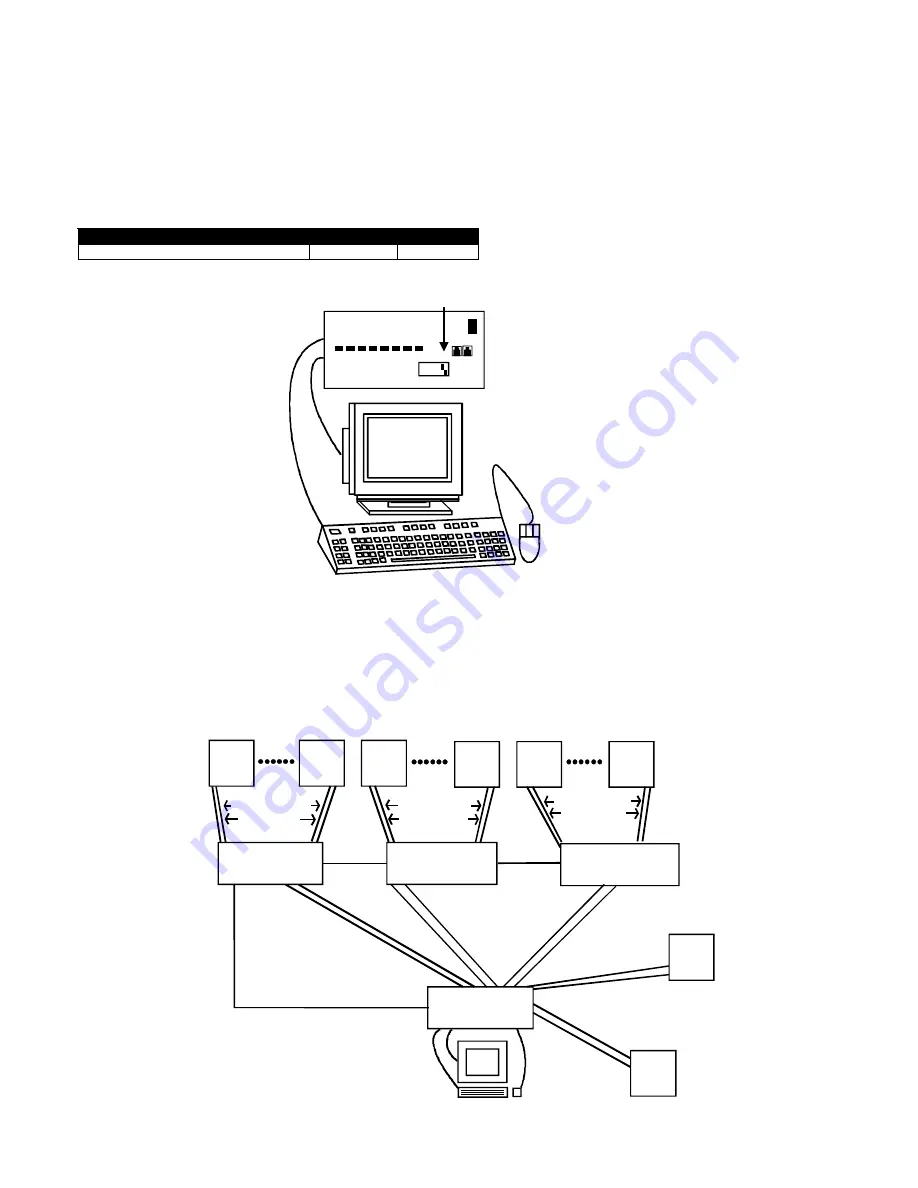
the following diagram for instructions on proper keyboard dip-switch configuration.

Keyboard dip-switch configuration

Table 1  (* default settings)

Keyboard / Mouse type

SW7

SW8

SUN*

ON

OFF

CASCADING

The SUN switch can be expanded to access up to 128 CPU’s by cascading multiple units together. Up to 8 SUN switches can be
connected into another switches CPU ports, as illustrated below. The SUN switch connected to the monitor & keyboard must be
configured as the “MASTER” unit (via dip-switches). Any switches connected to the “MASTER” must be configured as “SLAVE”
units. All SUN switches are fully configurable for this expansion method, the only additional hardware required is a set of
keyboard, monitor & RMT extension cables for each “SLAVE UNIT” (see materials).

ON

OFF

17,

NETWO RK
TECHN OLO G IES
INC ORPO RATED

12345678

Switch 7 - ON
Switch 8 - OFF

SE-8M13W3-8-A

KEEMUX-S8

(slave unit 1)

(slave unit 2)

(slave unit 3)

(master unit)

SUN

SUN

SUN

SUN

SUN

SUN

SUN

SUN

REXT-SR-xx

REXT-SR-xx

REXT-SR-xx

SUCEXT-xx

SUCEXT-xx

SUCEXT-xx

SUKINT-xx-MM

SUKINT-xx-MM

SUKINT-xx-MM

SUCEXT-xx

SUKINT-xx-MM

SUCEXT-xx

SUKINT-xx-MM

SUCEXT-xx

SUKINT-xx-MM

SUCEXT-xx

SUKINT-xx-MM

SUCEXT-xx

SUKINT-xx-MM

KEEMUX-S8

KEEMUX-S8

KEEMUX-S8

Summary of Contents for KEEMUX-Sx

Page 1: ...yboard Control 5 SCAN MODE 5 BROADCAST MODE 5 Keyboard Updating 5 How To Disable Operating Modes 6 Technical Specifications 10 Troubleshooting 10 Warranty Information 10 17 NETWORK TECHNOLOGIES INCORP...

Page 2: ...ase from Network Technologies Inc MF male female connector INSTALLATION 1 Turn OFF power to all computers that will be connected to the NTI Switch before connecting or disconnecting any cables WARNING...

Page 3: ...uration Table 1 default settings Keyboard Mouse type SW7 SW8 SUN ON OFF CASCADING The SUN switch can be expanded to access up to 128 CPU s by cascading multiple units together Up to 8 SUN switches can...

Page 4: ...ttings SW2 SW3 SW4 MASTER SLAVE OFF OFF OFF 1 slave attached Unit 1 OFF OFF ON 2 slaves attached Unit 2 OFF ON OFF 3 slaves attached Unit 3 OFF ON ON 4 slaves attached Unit 4 ON OFF OFF 5 slaves attac...

Page 5: ...example t002 would set time out to 2 seconds Pxx Selects a specific port xx port number as a two digit number ex p01 p08 p15 etc NOTE YOU MUST EXIT COMMAND MODE TO TYPE TO A COMPUTER TO EXIT COMMAND M...

Page 6: ...9 to disable the desired mode s If the unit is in a plastic case the digital board is located on the bottom of the case requiring the user to partially disassemble the unit to gain access to the jump...

Page 7: ...the standoffs With it loosened grasp firmly the video board and front panel at the same time and slide the front panel up out of the slots in the plastic case that support it Once clear of the case pi...

Page 8: ...harge any static charge you may be carrying by touching any large metal object away from the KEEMUX Sx O 4 Firmly grasp the front and rear panel and slide the entire assembly out of the lower case 5 R...

Page 9: ...cess to re assemble the KEEMUX Sx or KEEMUX Sx O Be particularly careful about connecting the ribbons back to the headers they were removed from and to fully insert the ribbons to the headers Note The...

Page 10: ...YS TURN POWER ON IN THIS SEQUENCE WARRANTY INFORMATION The warranty period on this product parts and labor is one 1 year from the date of purchase Please contact Network Technologies Inc at 800 742 83...

Reviews: