www.nationalrailwaysupply.com
1-800-357-3572
7
38933C
Relay Terminal Remote Wiring
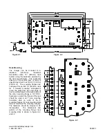
The OPEN, COMMON, and CLOSED relay contacts
have push-in type terminals for remote wiring. The
relay contacts are rated for 1A at 30 Vdc or 0.5A at
120 Vac. A small screwdriver (3/32 inch maximum
blade width) is required to insert or remove a wire
from a relay terminal.
WARNING:
BE
CAREFUL!
IF
AN
UNINSULATED METAL TOOL CONTACTS BOTH
THE GROUNDED CHARGER CASE AND A RELAY
TERMINAL PUSH-IN TAB, THIS WILL CAUSE A
POTENTIALLY
DAMAGING
AND/OR
DANGEROUS ELECTRICAL SHORT.
Table 10.1 outlines the operation of the LEDs and
alarm relay based on the status of the voltage
monitor. All relay contact states are with reference
to the terminal strip COMMON. The voltage
monitor/alarm is DC powered, so, if the charger
loses AC power, the voltage monitor/alarm will
continue to function on battery power until the DC
voltage falls below approximately 7.1 volts, where it
will continue to be in an alarm state until AC power is
returned to the charger and the charger is able to
raise the DC voltage above the LOW VOLTAGE (LV)
SET POINT setting.
Voltage Set Point Adjustments
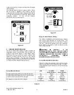
The HIGH VOLTAGE (HV) SET POINT setting is
adjustable with three (3) rotary switches and the
LOW VOLTAGE (LV) SET POINT setting is
adjustable with three (3) rotary switches, all of which
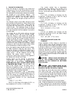
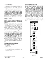
are available on the front of the charger (see Figure
10.1). For both settings, the top switch sets the tens
of volts, the middle switch sets the volts, and the
bottom switch sets the tenths of volts. Both set
points are settable between 07.8 and 51.3 volts. To
set the switches, use a small screwdriver to turn the
switch so that the arrowhead on the slot is pointing to
the desired number.
BE SURE EACH SWITCH IS
SET ON A NUMBER AND NOT BETWEEN
NUMBERS
. If a switch is set between numbers, the
corresponding LED will flash, and the voltage
monitor/alarm will not function as intended.
Voltage Monitor Battery Sense Input (Optional)
The voltage monitor/alarm includes an optional
VOLTAGE MONITOR BATTERY SENSE input
available on the front of the charger (see Figure
10.1). If the VOLTAGE MONITOR BATTERY
SENSE input is left disconnected, the DC voltage is
monitored internally at the charger output. The
VOLTAGE MONITOR BATTERY SENSE input can
be remotely wired to the terminals of the battery to
monitor the voltage at this point. The voltage
monitor/alarm
detects
when
the
VOLTAGE
MONITOR BATTERY SENSE input is connected to
the battery terminals and automatically monitors this
DC voltage instead of the voltage at the charger
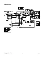
output. Please refer to the wiring diagram in Section
15 for the VOLTAGE MONITOR BATTERY SENSE
input connector detail.
Voltage Monitor/Alarm Specifications
RELAY CONTACT RATINGS:
1A at 30 Vdc
0.5A at 120 Vac
TERMINAL CONNECTIONS:
20
– 16 AWG wire, stripe length of .312 - .359 inches
(8
– 9 mm)
Voltage Monitor Status
BELOW HV
SET POINT
LED
ABOVE LV
SET POINT
LED
CLOSED
Relay Contact
OPEN
Relay Contact
DC voltage is below the HIGH VOLTAGE
(HV) SET POINT setting and above the LOW
VOLTAGE (LV) SET POINT setting
(normal
operation state)
On
On
Closed
Open
DC voltage is above the
HIGH VOLTAGE
(HV) SET POINT setting and above the LOW
VOLTAGE (LV) SET POINT T setting (
high
DC voltage alarm state
)
Off
On
Open
Closed
DC voltage is below the
HIGH VOLTAGE
(HV) SET POINT setting and below the LOW
VOLTAGE (LV) SET POINT setting (
low DC
voltage alarm state
)
On
Off
Open
Closed
Table 10.1


