background image

NRG Systems


Spidar User Manual


  Rev. 3 


4 November 2020 


Spidar User Manual 

nrgsystems.com | Page 31


d)


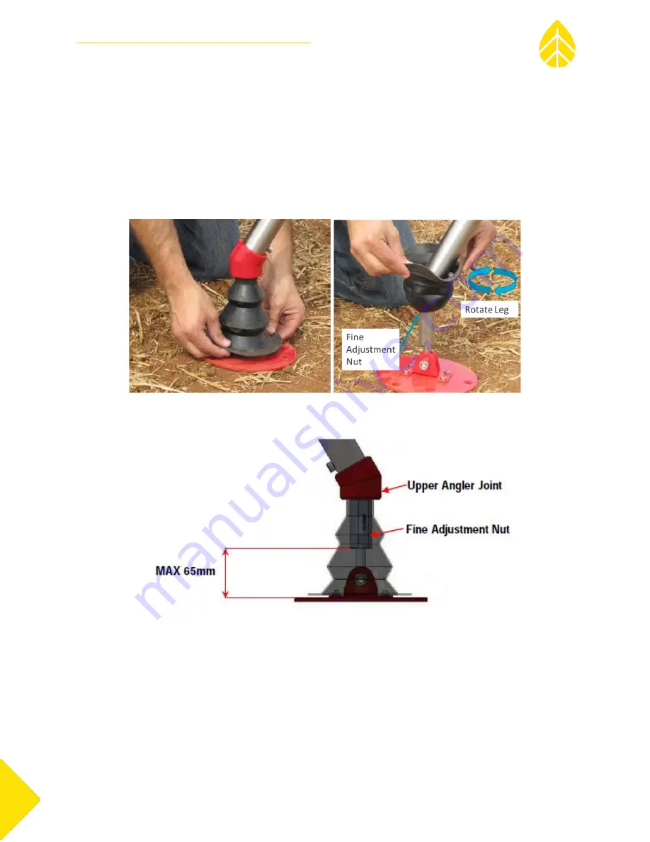
Using the built-in Spirit Level, determine which tripod leg(s) require fine adjustment to 

bring the Spidar into plumb. Spidar is plumb when the spirit level air bubble is within the red 
circle. 

e)


To make an adjustment, fold up the rubb

er ‘sock’ on the appropriate

 leg and rotate 

the base assembly on the fine adjustment nut to bring the Spidar to plumb. The Fine 
Adjustment nut must remain aligned flush and perpendicular to the Upper Angler Joint. 


Figure 35: Fine Adjustment Nut Location 


Figure 36: Spidar Foot Assembly 

f)


Check your spirit level to confirm the Spidar is plumb. Repeat steps D and E as needed. 

C.


Anchoring 

Anchor the Spidar is important to ensure that the system remains fixed in position and plumb during 
your measurement campaign. Insert an anchor rod through the outer hole of each foot pad and force 
the anchor into the ground. 

Summary of Contents for Spidar

Page 1: ...November 4 2020 ...

Page 2: ...mal Installation Dimensions 9 B Minimum Installation Dimensions 10 C Maximum Installation Dimensions 11 IV SPIDAR SPECIFICATIONS 12 A System Verification 12 B Verified Wind Measurement Performance 12 C System Geometry 12 D Hardware Specifications 12 E Electrical Specifications 12 F Data Specifications 12 G Environmental Specifications 13 H System Options 13 I Service Options 13 V UNPACKING 14 A Sp...

Page 3: ...2 1 Determining Azimuth Angle 32 E Meteorological Sensor 33 F Spidar Power Controller 34 1 AC Power Connections 34 2 DC Power Connections 35 3 Power Controller to Spidar Connections 37 4 Installing SIM Card in Spidar Power Controller PC 38 5 Connect and Confirm Spidar Power Controller Operation 41 6 Setting SIM Card APN 42 7 Confirm Power Controller PC Configuration 43 G Spidar Setup and Operation...

Page 4: ...ta Filtering 60 1 Data Quality Indicator Inputs 61 2 Setting a Data Quality Threshold 61 3 TI Filtering Error Bookmark not defined IX SPIDAR TO METEOROLOGICAL TOWER CORRELATION GUIDELINES 63 A Introduction 63 B Positioning the Spidar near the Meteorological Tower 63 C Data Filtering Procedure 63 1 Spidar Data Filtering 63 2 Met Mast Data Filtering 63 3 Time Stamp Alignment 64 D Data Correlation Me...

Page 5: ...ting wind shear validation horizontal uncertainty reduction and as a permanent met mast replacement on operating wind farms B Direct Detect Lidar and the Cross Correlation Method Laser pulses from one Spidar beam sample the atmosphere The reflected intensity of these pulses are received analyzed and sampled in time The sampled time series represents the aerosol density in the line of sight of the ...

Page 6: ... Spidar beam sample the atmosphere The same aerosol density signature is identified This establishes the time of flight between the two beam locations Combined with the known distance between the two locations Spidar is able to determine both wind speed and direction Figure 3 Spidar Pulsed Sampling at a Second Beam Location ...

Page 7: ... carry a Class 1 M label mentioned Do not Stare directly with Optical Instruments B Laser Safety Warnings C Laser Safety Requirements The Spidar laser source classified as class 4 is assembled inside a metal protective housing and an additional external envelope that is enclosing the Laser beam inside the protective housing The only laser beam is the Class 1M Laser beam that is projected by the ho...

Page 8: ... voltage rating is 110V to 220V AC 50 60 Hz Before servicing the Spidar ensure turning off the power to the system by switching the ON OFF key to the OFF position Each Spidar has a case to enable safe transportation of the system It is recommended that at least two people are used to lift and carry them due to their size and weight 75kg 165lb Each Spidar has a case to enable safe transportation of...

Page 9: ...ms Spidar User Manual Rev 3 4 November 2020 Spidar User Manual nrgsystems com Page 9 III SYSTEM OVERVIEW Figure 4 NRG Spidar System Overview A Optimal Installation Dimensions Figure 5 Optimal Installation Height ...

Page 10: ...r Manual Rev 3 4 November 2020 Spidar User Manual nrgsystems com Page 10 Figure 6 Optimal Installation Footprint B Minimum Installation Dimensions Figure 7 Minimum Installation Height Figure 8 Minimum Installation Footprint ...

Page 11: ...G Systems Spidar User Manual Rev 3 4 November 2020 Spidar User Manual nrgsystems com Page 11 C Maximum Installation Dimensions Figure 9 Maximum Installation Height Figure 10 Maximum Installation Footprint ...

Page 12: ...979 WS Deviation m s 0 04 10 m s WS Deviation 0 40 C System Geometry Full Cone Angle 10 Measurement Height Range 20 200m Number of Range Gates 10 Range Gate Heights Configurable D Hardware Specifications Warranty 2 years see NRG warranty statement Maximum Site Slope 20 Dimensions Typical footprint 1 092mm x 1 259mm x 1 425mm 43 x 49 6 x 56 1 Weight Shipping Crate 136kg 300lbs 1 118mm x 889mm x 1 0...

Page 13: ...munications User Interface and Power Control Module Included Power Supply Trailer PV Fuel Cell Genset Storage etc Available Temperature Barometric Pressure Precipitation Sensors Included Cellular Communications Available Satellite Communications Available Location Clock Synchronization GPS Included Wiper Fluid Reservoir 4 2L Included I Service Options Technical Support Included User Interface via ...

Page 14: ...tallation Flow Chart B Package Integrity Visual Inspection Before unpacking the Spidar from its shipping crate verify the crate integrity stickers documents and markings Verify that the TiltWatch tilt indicator and the Shockwatch shock indicator are not colored red Red indicates that the crate has been tilted or has undergone an excessive impact If any damage has occurred during shipping please co...

Page 15: ...age 15 Figure 12 Tilt and Shock Indicators Figure 13 Crate Shipment Integrity Features C Opening the Crate 1 Removing the Upper Cover Unscrew the four screws located on the upper cover side boards using a Posidrive head screwdriver Remove the upper cover carefully and place it to the side ...

Page 16: ...6 Figure 14 Shipping Crate Upper Cover 2 Removing the Protective Beam Unscrew the four screws located either side of the protective beam using a Posidrive head screwdriver Remove the crossbar carefully and place it to the side Figure 15 Shipping Crate Protective Beam 3 Removing the Front Panel ...

Page 17: ...h Step 2 unscrew 20 screws Remove the side panel carefully and place it to the side Figure 16 Shipping Crate Front Panel D Unpacking the Crate 1 Removing the Spidar Main Body Remove the Spidar main body lifting carefully by its red handles Only lift the Spidar by its red handles Safety shoes must be worn when installing the Spidar ...

Page 18: ...NRG Systems Spidar User Manual Rev 3 4 November 2020 Spidar User Manual nrgsystems com Page 18 Figure 17 Spidar Main Body Accessory Boxes Figure 18 Removing Spidar Main Body from Crate ...

Page 19: ...he three cardboard boxes from the main crate please see Figure 12 Box 1 size 75 30 15 cm Box 2 size 28 22 12 cm Open the three boxes and verify that all parts are present Description QTY Box Picture Spidar Main Body 1 NR Box 1 Tripod Leg Subassembly 3 1 Tripod Base Subassembly 3 Anchor Pins 3 Wiper Blade 1 External Wiper Fluid Pump 1 ...

Page 20: ...NRG Systems Spidar User Manual Rev 3 4 November 2020 Spidar User Manual nrgsystems com Page 20 Tool Kit 1 Screw Set 1 Box 2 Met Sensor 1 2 Box 3 Spidar Power Controller 1 3 Figure 19 Spidar Components ...

Page 21: ... support rod on each telescopic tripod leg assembly Figure 20 Tripod Leg Subassembly Figure 21 Tripod Base Subassembly c Assemble the three tripod subassemblies legs as seen in Figure 16 The tripod leg inner sleeves are marked engraved indicating optimal and max extension leg lengths Set all legs according to the area condition and snow feasibility In heavy snow condition it is recommended to exte...

Page 22: ...the Spidar main body Each of the tripod legs should be inserted into the leg sleeves and screwed on tight a Slightly tilt the Spidar to insert an assembled telescopic legs into a sleeve by gripping the leg support rod to enable free rotation for screwing the leg tightly into position The Spidar weighs approximately 50kg Use two technicians to remove and maneuver the Spidar from the shipping crate ...

Page 23: ... User Manual Rev 3 4 November 2020 Spidar User Manual nrgsystems com Page 23 Figure 23 Tripod Assembly b Repeat for all 3 legs Two people are needed one should hold and tilt the Spidar while the second connects the legs ...

Page 24: ...ystems Spidar User Manual Rev 3 4 November 2020 Spidar User Manual nrgsystems com Page 24 Figure 24 Final Leg of Tripod Mounting c Remove the Allen screw from a support rod Figure 25 Remove Support Rod Screw ...

Page 25: ... Page 25 d Position the support rod between the chassis and the telescopic leg and insert and tighten the Allen screw Rotate the tightening nut for proper tension in order to reduce stress from the chassis Figure 26 Connect and Adjust Support Rod e Repeat steps C D for all 3 support rods ...

Page 26: ...nces given the height of a potential obstruction such as a met tower buildings or trees The offset distances shown are based solely on the cone angle of each device Note that additional setbacks are required for sodars in order to prevent echoes from fixed objects from interfering with measurements Spidar has the smallest cone angle of any remote sensor in the wind industry allowing it to be sited...

Page 27: ...Table 1 Spidar Offset Distances B Elevation Leveling This section describes how to set the height of the Spidar above level ground The Spidar can be installed with a range of total system heights from 912mm up to 1 305mm The best height for your installation will depend on site conditions particularly how level it is and the expected snowfall 1 Remove Surface Obstructions Roughly level the Spidar ...

Page 28: ...d clearance for normal operation by extending its telescoping legs For installations in areas likely to experience heavy snowfall the Spidar should be installed with maximum possible ground clearance to minimize potential obstruction by snow and ice Figure 29 Maximum Ground Clearance The tripod leg inner sleeves are marked engraved indicating optimal and max extension leg lengths to aide this proc...

Page 29: ...rgsystems com Page 29 Figure 30 Spidar Leg Engraving The Spidar has a built in spirit level to enable precise leveling The Spidar is plumb when the spirit level air bubble is within the red circle Figure 31 Spirit Level and Spirit Level Cover Figure 32 Spirit Level Location ...

Page 30: ...elescopic tripod legs as necessary to achieve rough leveling The three legs should be different lengths when installing on an uneven surface to achieve rough leveling Figure 33 Adjusting Leg Length b After roughly leveling the Spidar tighten with an Allen key c Tighten the Allen screws affixing the support rods Figure 34 Tightening Support Rod Screw ...

Page 31: ...tate the base assembly on the fine adjustment nut to bring the Spidar to plumb The Fine Adjustment nut must remain aligned flush and perpendicular to the Upper Angler Joint Figure 35 Fine Adjustment Nut Location Figure 36 Spidar Foot Assembly f Check your spirit level to confirm the Spidar is plumb Repeat steps D and E as needed C Anchoring Anchor the Spidar is important to ensure that the system ...

Page 32: ...entation relative to north which is important to enable accurate wind direction measurements The azimuth angle is the angular difference between compass north and the Spidar s orientation and should be measured during commissioning and recorded in the system s configuration information A custom jig is provided to aide in this process 1 Determining Azimuth Angle Figure 38 Orienting the Spidar ...

Page 33: ...ighly recommended to verify the results by having a second person repeat steps A through D above for confirmation E Meteorological Sensor This section describes the installation of the combined temperature and precipitation sensor met sensor that comes with each Spidar system a Unscrew four Allen screws fastening the brackets located at the back of the converter and open the brackets b Position th...

Page 34: ... outlets CAUTION The following instructions require working with AC and DC electricity Only trained technicians with the proper experience should work with these power supplies Please use caution when working with the Power Controller Required cable specifications Max rating 16A 250V AC Minimum 5m cable length with local electrical plug on one end most quality extension cords will work Cut one end...

Page 35: ...nto port P1 in the Spidar s connection panel Skip to section ADD SECTION for the next steps 2 DC Power Connections When using a Photovoltaic PV and Battery power supply the Spidar Power Controller needs to be wired differently The following instructions explain how to wire the Power Controller 1 Unscrew the second strain relief port from the left and push the gasket out 2 Cut four slices in the ga...

Page 36: ...ve leads from the terminal blocks Tape the ends and secure the wires out of the way to make room for the PV and battery leads 5 Wire PV leads into the first terminal block on the left PV Input 6 Wire Battery leads into the middle terminal Battery Input Figure 43 Wiring of battery and PV inputs negative wire highlighted with gray arrow for contrast 7 Tighten strain relief and make sure everything i...

Page 37: ...eaker middle 2nd PV circuit breaker left 3rd load Spidar circuit breaker right 3 Power Controller to Spidar Connections To access the connection panel locate it along the base of the Spidar and unscrew the four Allen screws using a 3mm Allen Screwdriver This will release the cover and allow you to lower it exposing the connections underneath Figure 44 Opening Electrical Connection Panel 1st 2nd 3r...

Page 38: ...e the electrical connection panel and the USB cable run from connection panel into the Spidar Power controller and plugged into one of the USB ports This will allow Technical Services to update software and troubleshoot via RS232 if needed 4 Installing SIM Card in Spidar Power Controller PC The Spidar Power Controller comes with a modem embedded in the Power Controller PC The following instruction...

Page 39: ...adapter no need to undo the red and black wires 2 Remove the PC from the DIN rail by locating the latch at the bottom of the PC and using a screwdriver to pull it towards the bottom of the pelican case 3 Place the PC upside down and undo the 6 Phillips screws that hold the cover down 4 Remove the cover slowly because it is still connected to the inside to the PC 5 Unclip the modem wires from the s...

Page 40: ... out 9 Insert the SIM card with the contacts down and the notch in the upper left corner 10 Lay the SIM card tray flat and slide it forward to lock it into place 11 Insert the modem back into its slot and secure it with the screw 12 Clip the modem wires back into the wire holder 13 Place the cover back onto the PC and secure it with the 6 screws 14 Install the PC into the Pelican case Align top of...

Page 41: ...M card s APN FUSE exe used to retrieve data from the Spidar and uploaded it to NRG s cloud server FileZilla used to set the Spidar s configuration and manually retrieve data files and LOGs TeamViewer used to connect to the Power Controller and Spidar remotely There are a handful of other applications loaded on the Spidar Power Controller PC for troubleshooting There are two ways to connect to the ...

Page 42: ...pidarCtrl00xx see serial number sticker on the Power Controller case User VAR Password direct detect 6 Setting SIM Card APN Once connected to the Spidar Power Controller the SIM card s APN information need to be entered in the Skylight App 1 Locate the Skylight App on the Power Controller PC s desktop and double click on it 2 Click on the wrench icon to access the settings 3 Right click on Profile...

Page 43: ...er Controller will need to be connected to the Spidar via Ethernet and the Spidar will need to be powered on in order for it to work properly TeamViewer Locate the TeamViewer shortcut on the desktop or at C Program Files x86 TeamViewer 1 Double click on the icon to open the application a pop up might say it s already running this is okay 2 When the application opens it should show YOUR ID and PASS...

Page 44: ... the following procedures Powering on the Spidar Filling Water Configuring the Spidar Using the Spidar Admin Tool application H Powering on the Spidar After all power and communication cable connections have been established the Spidar can be powered on by a switch located in the Electrical Connection Panel Figure 46 Spidar Power Switch I LED Status Indicator The Spidar has a three color LED statu...

Page 45: ... Spidar maintenance it is necessary to verify sufficient Anti Freeze liquid and proper function of the wiping system every two months to six months While anti freeze can be used in cold climates we recommend using a mixture of water and isopropyl alcohol to lower the freezing point of the water The table below provides a rough guideline Minimum Temperature Percent Water Percent Isopropyl 3 C 90 10...

Page 46: ...oon as the electrical connection is made with the Spidar powered on 7 The pump will continue pumping until power is removed i e the gray cable is disconnected from the Spidar 8 Once the reservoir is fill the excess liquid will drain out of the bottom of the Spidar a Verify that the blue tubing is visible from the bottom of the Utility Panel opposite side from the Connection Panel where the pump is...

Page 47: ...age 47 9 When water starts leaking out of the bottom drain tube disconnect the power wire from the Spidar Remove the pump dry it and store the pump in the Spidar transport case 10 With a full reservoir the LED Status Indicator should turn green indicating the Spidar is ready for operation ...

Page 48: ...tructions 1 Enter the Host 192 168 1 1 Username Pentalum Password xphhsr and Port 21 in FileZIlla and click Quickconnect 2 The right section of the screen labeled Remote Site refers to the file structure inside the Spidar Navigate to Storage Card CONFIG SiteParameters cfg 3 Right click on the SiteParameters cfg file and choose View Edit NOTE DO NOT EDIT THE SiteParameters cfg OR ANY OTHER FILE WIT...

Page 49: ...e gates and measurement heights 6 Set the direction offset if the unit is not aligned north 7 NRG strongly recommends NOT changing the Time Reference for output files to be at the end of the 10 minute interval 8 Spidar units are programmed to create 10 minute averages by default The averaging interval can be modified but the minimum averaging interval should be 5 minutes 300 9 If using Modbus set ...

Page 50: ...turn the power off wait 1 minute and then on the Spidar back on Alternately the power relay in the Spidar Power Controller can be used by navigating to 192 168 1 7 in Firefox 14 Once the Spidar has been turned back on navigate back into FileZilla and verify that the changes made to the SiteParameters cfg are still present L Finalizing Spidar Installation With everything finalized at the site the f...

Page 51: ...gnal Tab NOTE the above image shows a typical Spidar Beam Signal Contact NRG Technical Services with questions or if the beams are falling outside of the dotted lines if this is the case the Spidar likely needs a mirror adjustment b If using 10 minute averages the Wind tab will provide average data points every 10 minutes with AVG selected instead of RAW c DO NOT CHANGE OTHER VALUES OR CLICK OTHER...

Page 52: ... choose View Edit to review the file in Notepad b Or choose the files you want to move over to the Power Controller PC and choose the location you want to download them to in the left Local site window Drag the files from the right screen to the left or right click on the data files and choose Download 4 There will only be a couple 10 minute average entries depending on how long the Spidar was run...

Page 53: ...hat the batteries are at a healthy level 24 5 VDC Clean the PV panels off if they are directly check the battery bank to verify that they are secured and connected properly Check Cables Make sure all cabling wires are protected against the environment and animals and that they are not damaged Fill Wiper Fluid The Spidar s status lights will change to Yellow when the reservoir is 1 3 full Refill as...

Page 54: ...hing the glass A yearly change of the wiper is a general suggestion and therefore close attention should be paid to see if it should be replaced more frequently B Wiper Replacement Instructions The Spidar wiping system that consists of wiper arm and water nozzle which is used to clean the top window The wiping system is controlled by an algorithm based off the precipitation sensor and the Lidar be...

Page 55: ...November 2020 Spidar User Manual nrgsystems com Page 55 C Wiper Fluid Nozzle Service The Wiper Fluid Nozzle clips onto the wiper arm and can require maintenance to remove clogs If the nozzle gets clogged clear it with compressed air or a pin ...

Page 56: ...ar User Manual nrgsystems com Page 56 D Power off Spidar To power the Spidar off 1 Remove Connection Panel cover 2 Flip the power switch to OFF NOTE When rebooting the Spidar wait at least 1 minutes before turning back on Power Switch for Newer Spidar systems ...

Page 57: ... a site s wind resources An explanation of how the Spidar calculates wind speed and direction over a range of heights and some key terminology are presented The main section of this document provides information about the 10 minute average file generated by the Spidar and a step by step procedure for filtering the Spidar data It also outlines methods to analyze the results in various ways and guid...

Page 58: ...lphanumeric characters Location identification L character followed by 3 alphanumeric characters A character delimits the fields 3 Company Name A fixed string denoting the company name eg NRGS 4 File Type A 6 letters string denoting the type of the file The following options apply AVGWND 5 Date Format YYYY MM DD_ sequential number of a specific file within a day starting from 1 6 Extension CSV ZIP...

Page 59: ...inute using 2 digits Range 00 59 mmm Milliseconds within a second using 3 digits Range 000 999 5 Met Measurements Barometric pressure values represent the average pressure readings as received from the pressure sensor for the current time period at 1m above ground level Table 1 summarizes the barometric pressure sensor parameters Temperature values represents the average external temperature at 1m...

Page 60: ...ext 4 columns are reserved for vertical speed measurement results which are not currently available Data is filled with 0 s The next 4 columns are the horizontal wind direction measurement results Table 9 Wind Direction Data Structure dir_h_horz_min m s horizontal minimum direction in degrees for height h dir_h_horz_max m s horizontal maximum direction in degrees for height h dir_h_horz_mean m s h...

Page 61: ... of finding an optimal quality threshold 2 If this Qth results with data availability of 85 it is recommended to keep it as is and use it for the rest of the analysis done on this set of data 3 If the resulted data availability is lower than 85 it is recommended to reduce the value of Qth until the user gets data availability of 85 However this data set may contain singular points of low quality w...

Page 62: ... The quality score does not correspond directly to data availability i e when using filter of quality score 20 it does not mean that you have filtered out 20 of the data An optimal quality threshold is both site and customer dependent so there is not a standard value that is optimal in all cases ...

Page 63: ...mparison B Positioning the Spidar near the Meteorological Tower It is strongly recommended to position the Spidar as close as possible to the meteorological tower while remaining clear of known obstructions or obstacles such as guywires trees or other vegetation An easy rule of thumb to remember is 10 1 The Spidar needs to be 1m horizontally clear from an object for each 10m in height of the objec...

Page 64: ...atures can cause cup anemometers to stick or freeze and underreport wind speed Icing events can be identified by examining the standard deviation of mechanical wind direction vanes Periods where ambient temperatures are near or below 0 C and the standard deviation of vanes remains at a fixed value are likely icing events Data acquired during such periods should not be included in a correlation ana...

Page 65: ...ss divided by the maximum number of averages possible for the campaign duration 3 Wind Speed Correlation Methods One measure that quantitatively describes the agreement between two data sets is the correlation coefficient R This value ranges from 1 to 1 and denotes how well two sets of data track one another A correlation coefficient of 1 0 implies a perfect inverse correlation while a value of 1 ...

Page 66: ...resolve this sort the data by direction and either add or subtract 360 from one data set in the northern direction sector Once this is complete the correlation coefficient can be calculated correctly 6 Wind Rose Comparison The wind rose is a common method of representing wind direction data It allows the prevailing wind directions to be easily determined and they provide information about how vari...

Reviews: