Basic description of PCL series
-14-
(2) Manual pulsar input on the PCL
This is a function used to receive encoder signals from some other encoder than the feedback encoder on the
back of the motor. Then, pulses can be output from the OUT and DIR terminals. A manual pulsar is not used to
output pulses like a start command. However, as you turn the dial, the motor will rotate and the up/down
counter can count the amount moved.
The PCL can read pulsar signals on both the PA and PB terminals.
The input signal type can be A/B phase signals (90
˚
phase difference signals) or bi-directional pulses (positive
and negative direction pulses). When A/B phase signals are selected, you can set the multiplier to 1x, 2x, or
4x.
The PCL outputs pulses from the OUT and DIR terminals that are synchronized with the speed at which you
turn the dial. If a stepper motor is used, turning too fast may cause it to get out of step. Therefore, the PCL is
set so that it won’t output pulses at a high frequency, with the FH speed being used as the upper limit.
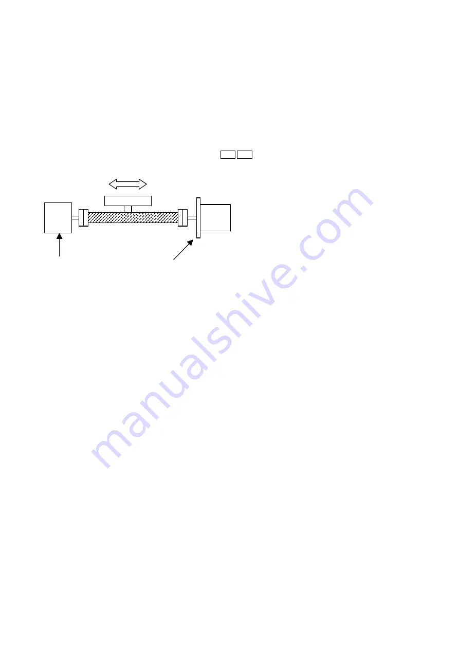
11. Stepper motor out-of-step detection function
50oo 60oo
This function detects out-of-step of stepper
motors.
To use this function, install an encoder with the
same resolution as the stepper motor on the
same axis as the stepper motor, as shown in
Figure 20.
The PCL compares the number of pulses output
by itself with the pulses returned from the
encoder. If the difference exceeds a preset value,
the PCL determines that an out-of-step condition
has occurred and its takes a specified action.
The action taken when an out-of-step condition
is detected varies with each model.
(1) PCL50oo series
This series stops the motor immediately and
outputs an INT signal. (The PCL50oo series has
a deflection counter for detecting an out-of-step
motor. This counter manages the deflection
amount.)
For example, if the maximum deflection detection amount is set to 5, when the difference between the number
of output pulses and returned pulses is 5 or less, the PCL considers that OK. If the difference is 6 or more, the
PCL declares that the motor is out-of-step and outputs an INT signal.
(2) PCL60oo series
This series detects an out-of-step condition using Comparator 3 and COUNTER3 (the deflection counter).
Therefore, the action taken when an out-of-step is detected can be selected from the actions available when
the comparator conditions are met. (Same as in section 9 (3) in Chapter III.)
The PCL50oo series has ERA/ERB terminals, exclusively for connecting an out-of-step detection encoder.
With the PCL60oo series, the EA/EB terminals are shared for use with an out-of-step detection encoder. Just
like with a pulsar input, you can choose the pulse style: A/B phase signals (90 phase difference signal) or
bi-directional pulse signals (positive and negative direction pulses). When A/B phase signals are selected, you
can set the multiplier to 1x, 2x, or 4x.
* The PCL61oo series does not have an out-of-step detection function.
What the PCL61oo series can do is as follows:
a) Count output pulses using COUNTER1.
b) Count encoder signals (EA/EB input) using COUNTER2.
<To check during operation>
c-1) During operation, latch COUNTER1 and COUNTER2 using the latch command, and then check the
difference between them using a CPU. (If you want to perform this check by using an interrupt, create a
program that will make this comparison at a specified interval using the comparator.)
<To check while stopped>
c-2) Check the COUNTER1 and COUNTER 2 values while stopped to determine if there was an abnormal
difference in the counts.
Encoder
(200 ppr)
2-pole HB type stepper motor
(2-2 phase excitation, 200 ppr)
<Figure 20>


