


Chapter2 Connection
Manual of NCH02
- 11 -
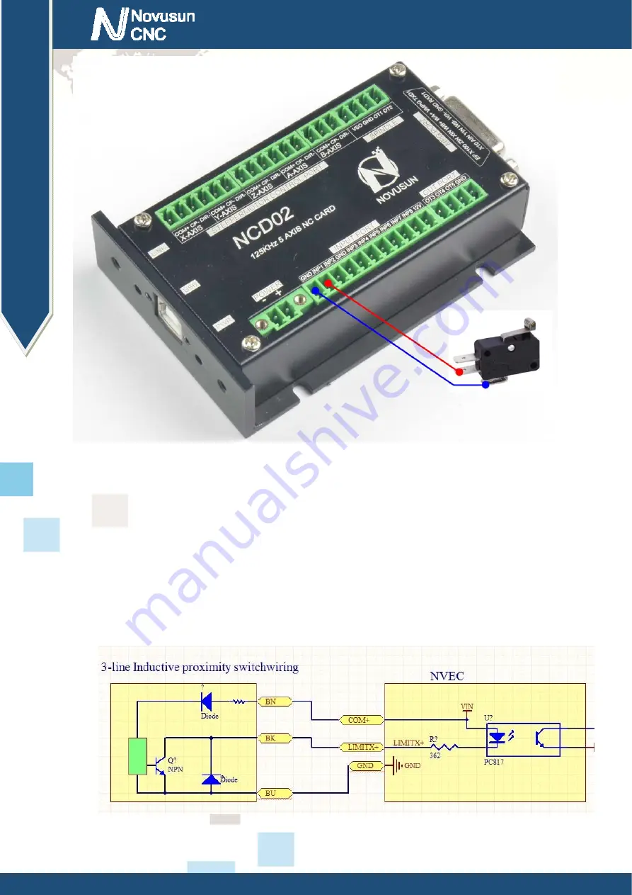
Figure2-5.
input interface serial number IN3 and 2 line proximity switch / common switch limit input
wiring diagram
3 lines Proximity Switch connection Figure 2-13,brown cable for Proximity switch connect
with 12V,Black cable connect channel, blue cable connect with GND1.
Only support NPN 3lines proximity switch.
Figure2-6.
NPN 3 lines Proximity Switch connection drawing
www.nvcnc.net


