


6.7 Geoid Model
The site to be used for the height of the system shall normally be based on the findings made with
respect to the Earth's surface gravity. The gravitational field isn’t everywhere the same, because
the planet's density varies depending on the mountains, deep seas and other forms depending on
the surface.
Differences in the height of the ellipsoidal system can be corrected by using the Geoid Model (Fig.
77). Geoid Model is a “net” which contains the needed correction data.
If the height difference between the Geoid and ellipsoid is significant, height of the ellipsoid needs
to be corrected. If Geoid Model is not available, the height of the ellipsoid can be corrected by
using a coordinate offset values.
6.8 GNSS accuracy test
When using the GNSS positioning, it is recommended to check its accuracy daily.
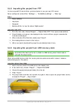
A known fixed checkpoint is required for the accuracy check. If there is no surveyor available to
measure the fixed point, the measurement can be done by using the GNSS receiver of the
machine.
Note!
If the checkpoint is measured with the GNSS receiver of the machine, only
calibration of the machine can be verified. A checkpoint measured by a surveyor is
needed for verification of the coordinate system.
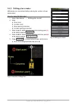
The way to check accuracy is to enter the known coordinates of the checkpoint into the
system.
1. Enter the known X, Y, and Z coordinates of the checkpoint into the system using “Log” tab
2. Select point tab
3. Choose the point that has been created
4. If there is single GNSS receiver, rotate the machine 360 degrees
5. Confirm that the system has an accurate RTK FIX status (when the background colour of
the status bar is green )
6. Place the bucket on the checkpoint
7. Confirm that the correct bucket measuring point is selected
8. The “Height deviation”, “Sideways distance”, and “Lengthwise distance” values on the point
tab should be close to zero. Typically the deviation should be no more than 2 cm vertically
and 3 cm horizontally (however, the accuracy required depends on the type of work and
type of machine)
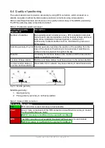
9. If the accuracy is not satisfactory, check the calibration of the bucket and the machine. Also
see section 6.4 “Quality of positioning”.
User Manual. Xsite PRO SPI 14.2 Page 69 / 77
Summary of Contents for XSITE PRO SPI 14.2
Page 1: ...XSITE PRO SPI 14 2 USER MANUAL Version 1 14 2 46 October 2018...
Page 33: ...Fig 36 Tilt bucket calibration User Manual Xsite PRO SPI 14 2 Page 30 77...
Page 76: ...User Manual Xsite PRO SPI 14 2 Page 73 77...
Page 77: ...User Manual Xsite PRO SPI 14 2 Page 74 77...


