background image

35

English

Programming a Pattern

To program a synth Pattern in Paraphonic Mode 1 (the default), first select a Patch as described 

in “Selecting Patches” on page 33. Enter 

Note View

 for Oscillator 1 (press 

Note

 and then 

Osc 

1

 if not already selected). 

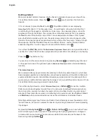
To assign a note to a Pattern step, press and hold the pad for the step – it will turn red – and 

simultaneously press the pad for the note to be assigned, which will also turn red while it is 

being pressed. For example, if you want your Pattern to start with the scale root note (which will 

be C unless you’ve changed it) on beat 1 of the Pattern, press and hold Pad 17 (the first step 

in the Pattern) and then press Pad 9. When you run the sequence, the note of C will now play 

on step1 of the 16-step Pattern. You can add further notes to other steps in exactly the same 

way. Note that once notes have been assigned to steps, the pads for those steps will illuminate 

bright blue. 

Note that the two 

Octave

 buttons 

13

 have no effect on the pitch of the notes once they’ve been 

recorded; you need to decide which octave you’re going to play in at the time of recording. 

However, you can still alter the octave of the pattern after recording by holding down 

Shift


when pressing 

Octave

.

The two parameters in 

Scales View

 – Scale and Root Note – can both be altered during 

playback as well, so if you like the pattern, but it’s in the wrong key to fit with another musical 

element, you can just press 

Scales

 and select a different root note.

Using Paraphonic Mode 2 (see “Paraphonic voicing” on page 26), exactly the same 

procedure can be used to program Steps for Oscillator 2.

Step editing

Step editing operations in Circuit Mono Station may either be done with the pattern running (i.e., 

in Play mode), or not running (i.e., in Stop mode).

Circuit Mono Station gives you the means of adding or deleting individual notes in a pattern 

without needing to worry about accurate timing, as editing is step-based and doesn’t require 

the notes to be accurately entered. 

All the following details apply equally – and independently - to Osc 1 and Osc 2. Press the  

Osc 1

 or 

Osc 2

 buttons to see the individual contributions of the two Tracks to the overall 

pattern. Bear in mind the need to select Paraphonic Mode 2 – by pressing 

Shift

 + 

Scales

 - to 

hear the Pattern assigned to Oscillator 2.

In 

Note View

 (but not 

Expanded Note View

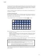
), the two lower rows of grid pads represent the 16-

step pattern and the two upper rows are the performance pads. When a pattern is played, you 

can see the white pad moving through the 16 steps. When a step has a note associated with it, 

the performance pad in the two upper rows corresponding to the note being played illuminates 

white while the note is sounding (but see the following page regarding octaves).

When the pattern is not playing, you can listen to the notes assigned to each step and alter the 

pattern manually. When the pattern is playing, you will only hear the notes associated with each 

step when the sequence gets to the step.

Summary of Contents for Circuit Mono Station

Page 1: ......

Page 2: ...ible steps to ensure that the information given here is both correct and complete In no event can Novation accept any liability or responsibility for any loss or damage to the owner of the equipment a...

Page 3: ...unit on 20 Getting started 21 The demo Sessions 21 Loading and Saving Sessions 22 Synth section basics 26 Paraphonic voicing 26 Tracks 27 Note View 27 Dual View 28 Expanded Note View 29 Scales 30 Scal...

Page 4: ...ck 55 Swing 56 Swing sync 57 Automation of Knobs and Sliders 58 SYNTHESIS TUTORIAL 59 CIRCUIT MONO STATION SYNTHESISER SECTION 71 Sound modification 71 LED parameter indicators 71 The Filter knob 71 P...

Page 5: ...n Matrix 82 Matrix assignment 83 The Distortion section 85 SYSTEM SETTINGS 86 MIDI I O 86 MIDI Tx Rx 86 MIDI Channel 87 Analogue Clock Rates 87 Pot Pickup 88 SESSION SWITCHING 89 Clearing Sessions 89...

Page 6: ...semble patterns together into longer chains and save your work in one of 32 session memories The synth section is reassuringly analogue the controls mostly a conventional and familiar set of single fu...

Page 7: ...k up your sessions and patches on line About This Manual We ve tried to make this User Guide as helpful as possible for all types of user both newcomers to electronic music making and those with more...

Page 8: ...e more advanced user and can generally be avoided by the novice They are intended to provide a clarification or explanation of a particular area of operation What s In The Box Circuit Mono Station has...

Page 9: ...wered from a computer or other device via a USB connection The AC adaptor supplied with the unit is a 12 V DC 1 25 A type and can operate on mains voltages from 100 V to 240 V 50 or 60 Hz The adaptor...

Page 10: ...de in pitch between each other as defined by the Glide time G Global View A View that allows editing of a whole Session Grid pad One of the 32 pads making up the main performance area Init Session The...

Page 11: ...n memory Where a Pattern is stored Pattern Settings View Pattern Settings A Pattern Edit View that allows the user to edit the length of a pattern for any Track set the playback direction and sync rat...

Page 12: ...ing the Note Velocity and Gate buttons Stop Mode Circuit s operating mode when the sequencer is not running Swing Shift Tempo Adds a subtle variation to the tempo alternate notes are shifted in time S...

Page 13: ...Master controls 1 Volume controls the overall level at the audio outputs 2 Tempo lets you set the BPM tempo of the sequence Hold down Shift to re assign it as a Swing control which will alter the tim...

Page 14: ...y Gate these switch the grid to Note Velocity and Gate View respectively and allow the parameters of each step of the pattern to be individually entered deleted or modified 7 Pattern Settings selects...

Page 15: ...Settings Mutate Randomizes the Steps in the current Pattern 13 Clear Duplicate Operates like a copy and paste function for Patterns or Steps 5 Osc 1 Key Tracking Causes the filter frequency to track...

Page 16: ...the available LFO waveforms triangle sawtooth square sample and hold The associated LED gives a visual indication of the LFO speed and waveform 22 Sync press to synchronise the LFO rate to the current...

Page 17: ...tion types I II and III Type I produces the distortion used in Bass Station II Type II is a fuzz type distortion Type III is a combination of the two 37 Level toggles between two filter slopes sets th...

Page 18: ...Each pulse applied advances the sequence by a quarter note Range 0 5 V to 5 5 V Sensitivity Below 1 V low Above 2 3 V high 6 NOTE OUT two 3 5 mm TRS jack sockets carrying Control Voltage CV and GATE...

Page 19: ...jack socket The headphone amplifier can drive 10 5 dBu into 150 ohms 12 Kensington security slot secure your Circuit Mono Station to a suitable structure if desired Please see http www kensington com...

Page 20: ...will re load the Session that was in use last time the unit was on The first time you power the unit out of the box this will be Session 1 which is the first of the 16 demo Sessions that were loaded...

Page 21: ...upper two rows of the grid each pad in Sessions View represents a Sessions Memory location The demo Sessions We recommend that you spend some time listening to the factory demo Sessions which have bee...

Page 22: ...4 to open this Each pad corresponds to one of the memory slots The pad s colour indicates the slot s status Dim blue slot is empty Bright blue slot contains either a Session saved by the user or a fac...

Page 23: ...in this case your work will be saved in the last selected Session memory which will most likely be the one that held an earlier version the earlier version will be overwritten To save your work in a d...

Page 24: ...looks like this PLAY Synth keyboard Pattern display The keyboard is two octaves with the purple pads representing the lowest and highest notes in each You can add synth notes in real time by just play...

Page 25: ...ght one which will turn red This gives the keyboard Chromatic scaling and the layout differs from that in the other scales C D C D F G A E F G A B C PLAY Synth keyboard Pattern display Chromatic scali...

Page 26: ...l this mode Paraphonic Mode 1 and it is the mode you will use when playing Circuit Mono Station in live performance or for recording This mode is confirmed by the Scales button 8 being lit dimly white...

Page 27: ...cy and so on More details can be found at The Modulation Sequencer on page 44 Programming the Modulation Sequencer Track referred to elsewhere in this Guide as Mod Seq is a very similar process to pro...

Page 28: ...ver two octaves in ascending order start with Pads 9 to 16 then 1 to 8 When Circuit Mono Station is powered up and an empty or new Session selected Middle C will normally be the lowest note of the two...

Page 29: ...of the selected scale Osc 1 Oct K Clear Save Sessions Mod Seq Osc 2 Oct J Osc 1 keyboard Osc 1 selected Osc 1 Oct K Clear Save Sessions Mod Seq Osc 2 Oct J Osc 1 Oct K Clear Save Sessions Mod Seq Osc...

Page 30: ...eated a pattern it s easy to get an idea of their effect and their differences Record a simple pattern of synth notes and then play it back using different scales You ll notice that with some scales c...

Page 31: ...31 Whole Tone 32 Chromatic The scale you choose to play in will be saved when you save the pattern You will see that when you select a different scale in Scales View the illumination of the pads in t...

Page 32: ...iew Root note The default root note for all scales is C In the Scales View shown at page 30 Pad 9 corresponding to C is lit a darker blue than the other pads To change the keyboard root note in Note V...

Page 33: ...ch View Page 1 Osc 1 Oct K Clear Save Sessions Mod Seq Osc 2 Oct J Osc 1 Oct K Clear Save Sessions Mod Seq Osc 2 Oct J The two pages are selected with the Oct J and Oct K buttons 12 In Page 1 Oct J is...

Page 34: ...ift 15 while pressing the grid pad this will simply select the Patch as normal Initial Patch You may sometimes want a very basic sound to work with To meet this need we ve provided an Initial Patch re...

Page 35: ...nother musical element you can just press Scales and select a different root note Using Paraphonic Mode 2 see Paraphonic voicing on page 26 exactly the same procedure can be used to program Steps for...

Page 36: ...d as long as the currently selected octave is the same as that used to record the note Remember that although you can t change the octave of a note once it s been recorded you can shift the octave of...

Page 37: ...inal note If you delete the original note and then enter the revised note you will find that the new note has the default values for Gate and Velocity You can also alter the duration Gate and Velocity...

Page 38: ...s three further parameters that are available to you to adjust These are Velocity which determines how the volume of a note is related to how hard the pad is struck Gate which sets the duration of the...

Page 39: ...value of 100 lies midway between two multiples of eight The table below shows the relationship between actual Velocity values and the pad display No of lit pads Velocity value No of lit pads Velocity...

Page 40: ...sents the time in the number of steps for which the notes at the step will sound Gate values are assigned to each note as you play the performance pads Circuit Mono Station quantizes them to the neare...

Page 41: ...a step and the illumination dims incrementally at each press Thus if a Gate duration of 3 5 was required for Step 1 the example above would look like this One step pad blinks blue white this is the st...

Page 42: ...fall or a rise in pitch according to whether the previous note was above or below the one at the step in question Glide settings are made in Glide View which is opened by pressing Shift 15 and Gate 6...

Page 43: ...on every note in the Pattern unless its value is changed at a subsequent Step So if you only want Glide at one Step you can assign the amount of Glide you want at that Step and then set Glide to zero...

Page 44: ...16 Modulation parameter value display Pattern step display Dark blue steps have notes assigned to them Although the value of the Modulation parameter is stored internally at 8 bit resolution 0 to 127...

Page 45: ...e has a fixed rate and thus at higher tempos and sync rates the modulation depth at the next Pattern step may not have time to reach the desired value When Smooth is active the Mod Seq button will lig...

Page 46: ...ngs View opened by pressing Pattern Settings 7 As well as defining the Pattern length Pattern Settings View also lets you choose the direction of the Pattern and set the Sync Rate for the Pattern The...

Page 47: ...mple View above Step 16 is the last Step in the Pattern and has no note assigned Press a different pad in the two lower rows of Pattern Settings View 17 32 to shift the end point to an earlier Step wh...

Page 48: ...ned by the two points by allowing for the loop round at the end In the example shown below the above example has the start point shifted to Step 3 so the Pattern is now only 10 Steps in length The col...

Page 49: ...adjusted to maintain the correct relative musical intervals Note that if the Sync Rate is changed while a Pattern is playing it will first complete its full cycle in the case of Forwards and Backward...

Page 50: ...anything it will be in the memory However each set of 32 Patterns will need to be saved as part of the current Session if you want to use the Patterns next time you power up Patterns View To see how...

Page 51: ...e last Step in the Pattern if Backwards direction is selected in Pattern Settings View You can restart the Pattern from the point at which the sequencer was stopped by pressing Shift and Play together...

Page 52: ...to chain four Patterns together on a Track press and hold the pad for the lowest numbered Pattern required and then press the pad for the highest numbered Pattern required For example if you want to...

Page 53: ...estart the Pattern from the point at which the sequencer was stopped by pressing Shift and Play together The above example illustrates the basic points involved in chaining Patterns together to make a...

Page 54: ...ment and is actioned by pressing the Shift and Pattern Settings buttons together The notes are assigned to different Steps and the Pattern will continue to loop around the defined Pattern Length using...

Page 55: ...6 seconds and the grid display reverts to the previous View External clock Circuit Mono Station may be slaved to an external MIDI clock Internal external clock selection is made in Settings View see...

Page 56: ...art Altering the Swing parameter from its default value of 50 the range is 20 to 80 alters the timing of odd numbered steps the off beats a lower swing value shortens the time between an odd beat and...

Page 57: ...interval is not achievable due to the restricted range of the Swing control Press and hold Shift 15 and Tap 3 simultaneously to see Swing Sync View Pad for current setting is lit white Default is Pad...

Page 58: ...e LED turns red to confirm that you are now recording the knob movement In order for the knob movements to be replayed you must drop out of Record Mode before the sequence loops right round otherwise...

Page 59: ...und and how the properties change over the duration of the sound With a musical synthesiser we deliberately set out to have precise control over these three properties and in particular how they can b...

Page 60: ...udness of the sound is determined by how large the vibrations are Very simply listening to a piano from a metre away would sound louder than if it were fifty metres away Volume A B Having shown that j...

Page 61: ...s reflect their actual shape when viewed on an instrument called an oscilloscope and they are Sine waves Square waves Sawtooth waves Triangle waves and Noise Each of Circuit Mono Station s Oscillator...

Page 62: ...series Square Pulse Waves Volume Harmonic 1 Sine Wave Sawtooth Wave Volume Volume Harmonic Square Wave Volume Harmonic 1 2 3 4 5 Volume Harmonic 1 3 5 7 Triangle Wave 1 2 3 4 5 Harmonic 1 2 3 4 5 Nois...

Page 63: ...re at the same volume Because it possesses no pitch noise is often useful for creating sound effects and percussion type sounds Volume Harmonic 1 Sine Wave Sawtooth Wave Volume Volume Harmonic Square...

Page 64: ...eresting harmonic mixes It is also possible to slightly detune one Oscillator against the other which creates a very warm fat sound Circuit Mono Station s Mixer allows you to create a sound consisting...

Page 65: ...the harmonics above the cut off point of a low pass filter How rapidly these harmonics reduce in volume as frequency increases above the cut off point is determined by the filter s Slope parameter Th...

Page 66: ...cy Cut off Frequency In addition to the traditional low pass filter type there are also high pass and band pass types On Circuit Mono Station the Filter type is selected with the Shape switch 30 A hig...

Page 67: ...ibes how the volume of the sound is controlled The volume of a note created by a musical instrument often varies greatly over the duration of the note according to the type of instrument For example a...

Page 68: ...d when the note is played Each envelope generator has four main parameters which determine the shape of the envelope these are often referred to as the ADSR parameters TIME VOLUME ATTACK DECAY RELEASE...

Page 69: ...volume and in pitch and timbre Sometimes these variations can be quite subtle but still contribute greatly towards characterising the final sound Whereas an Envelope is used to control a one off modul...

Page 70: ...te is played 5 LFOs and Envelopes that can be used to modulate any of the above Much of the enjoyment to be had with a synthesiser is with experimenting with the factory preset sounds Patches and crea...

Page 71: ...sudden change in parameter value and hence in sound when the pot is moved With Pot Pickup on a control needs to be moved to the physical position corresponding to the Patch s saved parameter value bef...

Page 72: ...pulse is output fractionally later than the CV voltage to permit external equipment to stabilise its pitch before the note is turned on Circuit Mono Station also has an AUX CV output 7 for connection...

Page 73: ...nge 16 Coarse 18 and Fine 19 set the Oscillator s fundamental frequency or Pitch The Range switch is calibrated in traditional organ stop units where 16 gives the lowest frequencies and 2 the highest...

Page 74: ...octave oscillator whose output can be added to that of Osc 1 and Osc 2 to a greater bass effect The sub oscillator s frequency is always locked to that of Osc 1 so that its pitch is exactly one octave...

Page 75: ...rces can be mixed together in various proportions to produce the overall synth sound using what is essentially a simple 6 into 1 mono mixer Each of the six sound sources has its own level control 23 t...

Page 76: ...er distortion effects unit Program an Osc 1 Pattern with a single note on Step 1 which sounds for the whole bar 16 Pattern steps this will keep the envelope open Turn all Oscillator level controls dow...

Page 77: ...ary Frequency control 32 sets the filter cut off frequency when Shape is set to HP or LP With a band pass filter configured Frequency sets the centre frequency of the pass band Sweeping the filter fre...

Page 78: ...histling effect to the sound Low Pass 12 dB with Resonance Low Pass 24 dB with Resonance Volume Frequency Cutoff Frequency Cutoff Frequency Volume Frequency Filter Key Tracking The cut off frequency o...

Page 79: ...F The ADSR envelope can be most easily visualised by considering the amplitude volume of a note over time The envelope describing the lifetime of a note can be split into four distinct phases Attack t...

Page 80: ...fully down will make the note inaudible when the decay time has elapsed Release Many sounds acquire some of their character from the notes remaining audible after the pad is released this hanging or f...

Page 81: ...gle falling Sawtooth Square or Sample and Hold The LEDs next to the switch confirm the waveform currently selected LFO Rate The speed or frequency of the LFO is set by the Rate control 20 The frequenc...

Page 82: ...Frequency Post filter Distortion Aux CV Output Osc 2 Pitch LFO AmpEnv Each matrix crosspoint can have its own level set from zero to maximum Modulation Sequencer The Modulation Matrix may be visualise...

Page 83: ...Oscillator currently selected by Osc 1 and Osc 2 buttons 5 2 Oscillator waveform must be set to Square Pulse for PWM to be active 40 38 39 The Depth control 40 determines the degree of control that t...

Page 84: ...ve and then fall below the normal frequency The effect of positive and negative values of Depth can then be best appreciated if LFO is set to an asymmetrical wave shape such as sawtooth Adding LFO Mod...

Page 85: ...7 The Type button 36 selects one of three analogue distortion types simply referred to as I II and III Type I uses the distortion circuitry found on the Novation Bass Station II synth Type II classic...

Page 86: ...tem Settings View is exited by pressing the Play button MIDI I O You can choose to transmit and or receive MIDI Note data MIDI CC Control Change data and MIDI clock independently When Circuit Mono Sta...

Page 87: ...Pattern independently from those for Oscillator 2 The pad colours reflect the selected Oscillator via the Osc buttons 5 The pad for the currently active MIDI channel is brightly lit while the others...

Page 88: ...y a low to high transition The input clock rate is fixed at 2 ppqn Pot Pickup The operation of Pot Pickup is described at page 71 It is enabled in System Settings View with Pad 24 which will be lit Ye...

Page 89: ...old down Shift while selecting a new Session the current Pattern will stop playing on the next step and switch immediately to the new Session The new Session will play from the same step in the Patter...

Page 90: ...d above not work correctly for any reason To enter Bootloader Mode 1 Turn Circuit Mono Station off 2 Hold down the Scales 8 Note 6 and Velocity 6 buttons 3 Power Circuit Mono Station on again Circuit...

Page 91: ...2 fine 0 centre Osc 2 range 8 A3 440Hz Osc 2 coarse 0 centre Osc 2 waveform saw Osc 2 shape pulse width 0 Osc 1 2 Sync Off Mixer Osc 1 level 100 Osc 2 level 100 Sub Osc level 0 Noise level 0 Ring mod...

Page 92: ...cted Session when it is powered up It is possible that if the power was interrupted while a session was being saved it may have become corrupted in some way This might mean that Circuit ends up in som...

Page 93: ...93 English...

Reviews: