


Chapter 2 SMART2 Installation
SMART2 Installation and Operation Manual 1
18
2.4 Connect I/O Signals to a SMART Antenna
The SMART Antennas has several outputs, also referred to as strobes, that provide status and
synchronization signals.
l
Pulse Per Second (PPS) output (E2 on SMART Antenna Interface cable)
l
Emulated Radar Output (E2 on SMART Antenna Interface cable)
l
Event Mark Input (MKI) (E2 on SMART Antenna Interface cable)
To access the I/O signals, connect the interface cable or a custom made cable, to the main 14-
Pin interface connector. Refer to
SMART Antennas Interface Cable (Optional Accessory)
page 73 for connector pin out and other details.
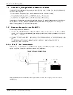
2.5 Connect Power to the SMART2
To connect power to the SMART2:
1. Connect the SMART2 Interface Cable (01019944) to the 14-Pin connector on the back of the
SMART2. See
SMART Antennas Interface Cable (Optional Accessory)
on page 73 for inform-
ation about this cable.
2. Connect the BATT+ and BATT- bare wires of the interface cable to a 7 to 30 VDC power sup-
ply.
For details about the power supply required, see
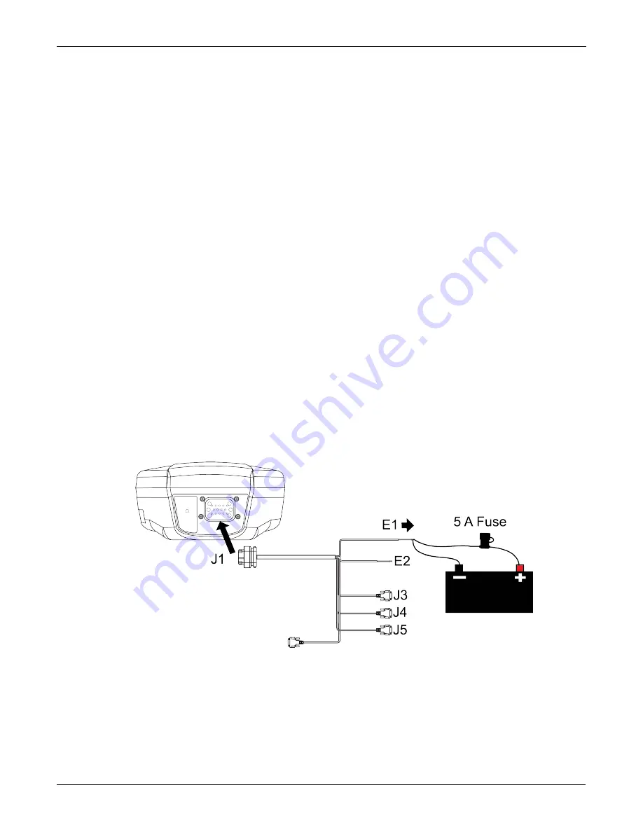
2.5.1 Fuse for the Power Supply
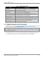
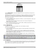
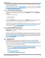
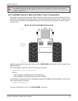
Install a user supplied 5 A slow blow fuse in the positive line of the connection to the power
source to protect the power supply wiring and your warranty.
Figure 5: Power Supply Fuse
Refer to
SMART Antenna Additional Equipment Required
on the next page for fuse recom-
mendations.