


Chapter 2 SMART2 Installation
SMART2 Installation and Operation Manual 1
15
SMART Antennas have an internal power module that:
l
filters and regulates the supply voltage
l
protects against over-voltage, over-current and high-temperature conditions
l
provides automatic reset circuit protection
If the voltage supplied is below the minimum specification, the receiver suspends
operation. If the voltage supplied is above the maximum specification, the receiver
may be permanently damaged, voiding the warranty.
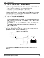
The supply must be capable of providing enough current to operate the
SMART Antenna, including the initial inrush transient. The supply must also be
current limited to 5 A with an external fuse.
The amount of power required depends on the number of constellations and signals
tracked, and the features enabled.
Refer to
SMART Antennas Interface Cable (Optional Accessory)
on page 73 for details about the
power cable.
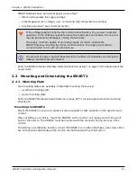
2.2 Mounting and Orientating the SMART2
2.2.1 Mounting Plate
Two mounting plates are available to facilitate mounting the receiver:
l
a surface mounting plate
l
a pole mounting plate
Refer to
SMART2 Mechanical Specifications
on page 67 for mounting plate and pole mounting
dimensions.
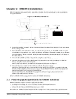
Mounting the SMART2
Mount the SMART2 on a secure, stable structure capable of safe operation in the specific envir-
onment.
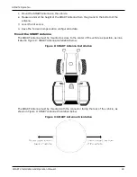
When installing on a vehicle, mount the SMART2 on the vehicle roof, ideally close to the pivot
point of the vehicle. The SMART2 must be mounted with the connector facing the rear of the
vehicle.
If installing in a stationary location, mount the SMART2 in a location that has a clear view of the
sky so that each satellite above the horizon can be tracked without obstruction.