Northern Lights M150A13 Operator'S Manual Download Page 57

OM3-80 12/21

Service As Required (Continued)

55

RG19661,00003F4 -19-20FEB13-1/1

Replacing Alternator Belt (With Automatic

Tensioner)

Refer to CHECKING BELT TENSIONER SPRING

TENSION AND BELT WEAR in Lubrication and

Maintenance/500 Hour/12 Month Section for additional

information on the belt tensioner.

CAUTION: Belt guard should be in place at all

times when engine is running.

NOTE: While belt is removed, inspect pulleys and

bearings. Rotate and feel for hard turning or

any unusual sounds. If pulleys or bearings need

replacement, see your John Deere dealer.

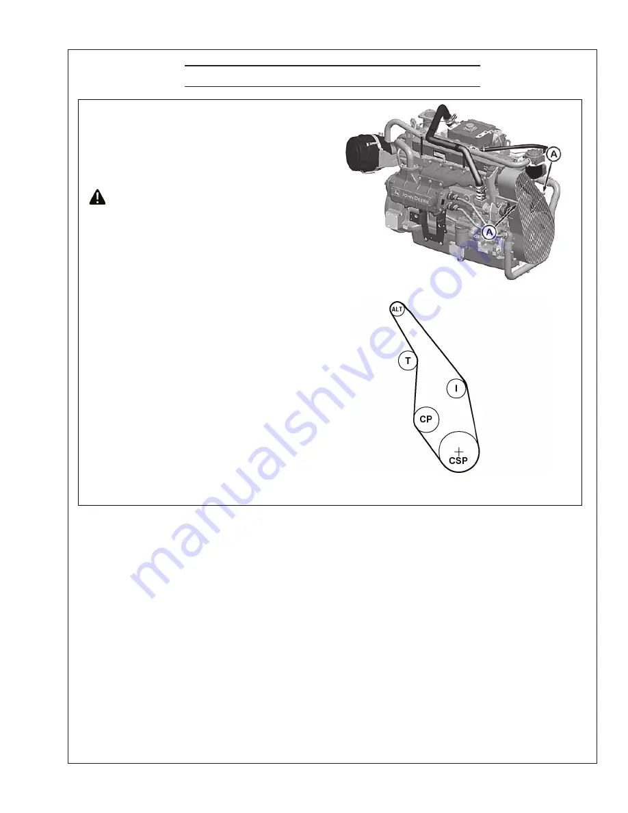
1. Remove cap screws (A) and carefully remove belt

guard from engine.

2. Release tension on belt using a breaker bar and socket

on tension arm and remove poly-vee belt from pulleys.

3. Inspect belts for cracks, fraying, or stretched out

areas. Replace if necessary.

4. Install new belt, making sure belt is correctly seated in

all pulley grooves. Refer to belt routing at right.

5. Apply tension to belt with tensioner. Remove socket.
6. Start engine and check belt alignment.

A—Cap Screws

ALT— Alternator

CSP—Crankshaft Pulley

I— Idler Pulley

T—Tensioner

CP—Coolant Pump

RG2216

2—

UN—06DEC12

Remove Belt Guard

RG1207

7—

UN—26FEB0

2

Belt Routing

Summary of Contents for M150A13

Page 1: ...OM3 80 For Models M80A13S M80A13 M99A13S M99A13 M150A13S M150A13 OPERATOR S MANUAL OPERATOR S MANUAL www northern lights com...

Page 2: ...o the outside Do not modify or tamper with the exhaust system Do not idle the engine except as necessary For more information go to www P65warnings ca gov diesel CALIFORNIA Proposition 65 Warning Nort...

Page 3: ...Control Units 18 Keeping Electronic Control Units Clean 18 SERVICE INTERVAL CHARTS Propulsion and Prime Power Units 20 Standby Generator Sets 21 LUBRICATION AND MAINTENANCE Daily Pre starting Checks...

Page 4: ...ern Lights equipment by serial number please refer only to the number stamped on the Northern Lights serial number plate Serial Numberss Model Numberss 2 Northern Lights Tier III turbocharged marine d...

Page 5: ...and clean condition Replace missing or damaged signs Be sure new equipment components and repair parts include the current safety signs For replacement signs proper placement of safety signs or clari...

Page 6: ...parts have stopped before making any adjustments connections or performing any other type of service to the engine or other driven equipment Prevent accidental discharge of starting fluids by storing...

Page 7: ...oisonous and strong enough to burn skin eat holes into clothing and other materials and cause blindness if splashed into eyes To Avoid Hazards Fill batteries only in well ventilated areas Wear appropr...

Page 8: ...paint and solvent properly Service Cooling System Safely WARNING Opening a pressurized cooling system can release explosive fluids and causing serious burns Before opening any pressurized cooling sys...

Page 9: ...ce components between the high pressure fuel pump and nozzles on engines with high pressure fuel systems ONLY AUTHORIZED TECHNICIANS CAN PERFORM REPAIRS ON AN HIGH PRESSURE FUEL INJECTION SYSTEMS Avoi...

Page 10: ...annot be achieved at the local supply valve shut off valves further back in the system and re check the bleed off point until complete shut off is achieved Affix a DO NOT OPERATE tag to each valve han...

Page 11: ...OM3 80 12 21 Notes 9...

Page 12: ...ll 4 Alternator 5 Belt Guard 6 Lube Oil Dipstick 7 Lube Oil Filter 8 Lube Oil Fill 9 Fuel Filter 10 DC Control Junction Box 11 Fuel Injection Lines 12 Starter 13 Thermostat Cover 14 Expansion Tank 15...

Page 13: ...the switch and it will return to RUN position To stop the engine hold the switch in the STOP position 3 OIL PRESSURE GAUGE The oil pressure gauge shows the oil pressure in the engine lubricating syste...

Page 14: ...s before adding load If the stand by generator set is loaded as soon as it reaches rated speed this procedure would not apply Operating 1 Check Gauges Often Oil pressure must be above 29 PSI if not ab...

Page 15: ...the exclusion of careful gauge monitoring Watching your gauges can prevent damage to the unit and dangerous power losses 2 Do the following when your shutdown system is activated a Check the temperatu...

Page 16: ...hours of operation with break in oil See GENERAL ENGINE SPECIFICATIONS in Break in Oil Operate the engine at heavy loads with minimal idling during the break in period idle constant speeds and or lig...

Page 17: ...rops quickly stop the engine and determine the cause before resuming operation A Coolant Temperature Gauge RG13133 UN 07OCT03 Coolant Temperature Gauge Electronically Controlled Engine Generator Set P...

Page 18: ...ment in rotating driveline can cause serious injury or death Keep shield on PTO driveshaft between clutch housing and the engine driven equipment at all times during Stop the engine and be sure PTO dr...

Page 19: ...ttery ies for 24 volt electrical systems 1 Connect booster battery or batteries to produce the required system voltage for your engine application NOTE To avoid sparks DO NOT allow the free ends of ju...

Page 20: ...welding reverse Steps 1 5 Keep Electronic Control Unit Connectors Clean IMPORTANT Do not open control unit and do not clean with a high pressure spray Moisture dirt and other contaminants may cause pe...

Page 21: ...OM3 80 12 21 Notes 19...

Page 22: ...se Ventilation Assembly Check Air Intake Hoses Connections System Replace Fuel Filter Elements Check Automatic Belt Tensioner and Belt Wear Check Cooling System Coolant Solution Analysis Add SCAs as r...

Page 23: ...Check Engine Mounts Replace Crankcase Vent Filter If Equipped Clean Crankcase Ventilation Assembly Check Air Intake Hoses Connections System Replace Fuel Filter Elements Check Automatic Belt Tensioner...

Page 24: ...1 Check engine oil level on dipstick A Add as required using seasonal viscosity grade oil See DIESEL ENGINE OIL in Fuels Lubricants and Coolant Section the dipstick Oil levels anywhere within crosshat...

Page 25: ...3AUG88 High Pressure Fluids RG22040 UN 28NOV12 Engine Top Tank IMPORTANT A restricted or clogged sea water strainer will result in hotter than normal or overheated engine coolant and marine gear oil t...

Page 26: ...essive coolant leakage may indicate the need to replace the water pump seal Contact your engine distributor or servicing dealer for repairs 6 Move switch to ON position and check instruments for prope...

Page 27: ...0 hours thereafter If John Deere PLUS 50 or ACEA E7 E6 E5 E4 engine change interval may be extended by 50 percent or to 375 hours IMPORTANT If using BIODIESEL blends greater than B20 shorten oil chang...

Page 28: ...ling Surface On Header F Dust Seal RG22045 UN 29NOV12 Oil Filter RG11617 UN 24OCT01 Oil Filter Seals RG22046 UN 29NOV12 OIl Filter Mounting Header Northern Lights RG19661 00003D4 19 28FEB13 3 3 9 Fill...

Page 29: ...ee batteries should require little additional service However electrolyte level can be checked by cutting the center section of decal on dash line and removing cell plugs If necessary add clean soft w...

Page 30: ...your skin with water 2 Apply baking soda or lime to help neutralize the acid 3 Flush your eyes with water for 10 15 minutes Get medical attention immediately If acid is swallowed 1 Drink large amounts...

Page 31: ...heat exchanger end cap and are mounted on hex head pipe plug 1 Remove zinc rod from each end cap B and observe condition of each apart when tapped install a new zinc plug A Zinc Plugs B End Cap RG221...

Page 32: ...gs need replacement see your John Deere dealer 4 If tensioner has been removed tighten tensioner mounting cap screw B to 70 N m 52 lb ft 5 Install belt guard A Belt Guard B Mounting Cap Screw C Tensio...

Page 33: ...nt Filter Checking Closed Crankcase Vent System 1 Inspect hoses A B C and oil drain line D for kinks blockage or other damage sure it is not plugged 3 Verify that the crankcase vent system bypass port...

Page 34: ...s from entering fuel system 3 Loosen drain plug and air vent screw Drain fuel into a suitable container clockwise 1 4 turn when viewed from the top to remove from base required be indexed properly wit...

Page 35: ...bottom of fuel tank not illustrated keep debris from entering fuel system 3 Disconnect water in fuel sensor 4 Drain fuel into a suitable container E required be indexed properly with slots in mountin...

Page 36: ...when automatic spring tensioner is used Measure tensioner spring tension using a torque wrench and procedure outlined below 1 Release tension on belt using a long handled 1 2 inch drive tool in square...

Page 37: ...serious burns cool enough to touch with bare hands Slowly before removing completely IMPORTANT Air must be expelled from cooling of cylinder head or plug in thermostat the air has been expelled 1 Chec...

Page 38: ...ps or a COOLSCAN or COOLSCAN PLUS analysis If a COOLSCAN or COOLSCAN PLUS analysis is not available recharge the system per instructions printed on label of John Deere Liquid Coolant Conditioner IMPOR...

Page 39: ...amount of inhibiting additives in your coolant and whether more John Deere COOLANT CONDITIONER should be added COOLSCAN Or COOLSCAN PLUS For a more thorough evaluation of your coolant perform a COOLS...

Page 40: ...ks Replace heat exchanger core as required 9 Remove and thoroughly clean water manifold heat exchanger housing if needed Install Heat Exchanger Core Thoroughly inspect condition of end cap sealing O r...

Page 41: ...ank Align core divider vertically with stamped note indicating This side up Core shown separated from cap for illustration purposes 5 Fasten rear end cap and core to tank with bolts and washers Tighte...

Page 42: ...cap and O ring 5 Remove clamps E and remove hoses from front cap 6 Remove four cap screws F front cap and O ring 7 Remove aftercooler core from the rear of the engine A Clamp B Clamps C Mounting Bolt...

Page 43: ...2 Fill tank with coolant to the normal operating level IMPORTANT DO NOT apply excessive pressure to cooling system doing so may damage coolant tank and hoses Cooling System Pres sure 110kPa 16 psi 4 W...

Page 44: ...and O ring 5 Remove clamps E and remove hoses from front cap 6 Remove four cap screws F front cap and O ring 7 Remove aftercooler core from the rear of the engine A Clamp B Clamps C Mounting Bolt D Ca...

Page 45: ...can cause serious burns cool enough to touch with bare hands Slowly before removing completely NOTE When John Deere COOL GARD is used the drain interval is 3000 hours or 36 months The drain interval...

Page 46: ...oing so may cause engine to overheat causing burns when cooling system is draining 8 Fill the cooling system with clean water Run the engine about 10 minutes to stir up possible rust or sediment 9 Sto...

Page 47: ...xhaust manifold 4 Remove cap screws F attaching thermostat housing to the exhaust manifold 5 Remove thermostat housing with gasket I Remove and disgard all gasket material Clean all sealing surfaces 6...

Page 48: ...DO NOT allow thermostat or thermometer to rest against the side or bottom of container when heating water Either may rupture if overheated 4 Suspend thermostats and a thermometer in a container of wa...

Page 49: ...Remove cam screw B holding cam plate to impeller housing bore RG9853 UN 05JAN99 Remove Cover Plate RG6243 UN 23MAR92 Inspect Sea Water Pump Impeller A Cover Plate B Cam Screw 6 Thoroughly clean impel...

Page 50: ...aligned Apply LOCTITE 242 to cam screw B install and tighten The cam plate should be inspected to insure that none of damage The cam screw should also be inspected to insure that it does not protrude...

Page 51: ...r in the middle of the blade If impeller replacement is necessary order an impeller repair kit IMPORTANT If impeller has chunks of material missing the heat exchanger aftercooler marine gear oil coole...

Page 52: ...ot recommended by the manufacturer will terminate the warranty obligation to the purchaser In addition tampering with fuel system which alters emission related equipment on engines regulations or othe...

Page 53: ...en adding coolant to the system use the appropriate coolant solution See TS281 UN 23AUG88 High Pressure Fluids ENGINE COOLANT SPECIFICATIONS in Fuels Lubricants and Coolant Section for mixing of coola...

Page 54: ...n or visibly dirty NOTE This procedure applies to John Deere air cleaner kits Refer to manufacturers instructions for servicing air cleaners not supplied by John Deere cleanings See following blocks l...

Page 55: ...t room temperature being oiled with oil provided in kit RE504585 motor oil diesel fuel or any type light weight spray lubricant These products will damage NOTE Red dye is added to oil to show areas of...

Page 56: ...or reset button A and release to reset indicator RG9927 UN 18NOV99 Air Restriction Indicator Reset Button Replacing Air Cleaner Filter Element IMPORTANT Replace the element after 10 cleanings RG9926 U...

Page 57: ...pulleys or bearings need replacement see your John Deere dealer 1 Remove cap screws A and carefully remove belt guard from engine 2 Release tension on belt using a breaker bar and socket on tension a...

Page 58: ...ers engine power to auxiliary equipment or moving components Proper performance of the power take off unit will be related to the care it is given Periodically check for any oil leaks that may occur T...

Page 59: ...leaks with a piece of cardboard Protect hands and If an accident occurs see a doctor immediately removed within a few hours or gangrene may result Doctors unfamiliar with this type of injury may call...

Page 60: ...Inspect gear teeth for damage Install new gear D by aligning key C to the pump shaft keyway insure key is properly in place 6 Tighten hex nut to 68 N m 50 lb ft 7 Install sea water pump with new gaske...

Page 61: ...rly If the ECU detects a problem with the electronic control failed system will be stored in the ECU s memory There are two types of DTCs Active Inactive Stored Active DTCs indicate that the failure i...

Page 62: ...ponents from welding may cause permanent damage 1 Remove paint from the area to be welded and ground cable clamp location 2 Disconnect the negative battery cable s or open battery switch if equipped T...

Page 63: ...Connector 10 Camshaft Position Sensor Connector 11 Low Pressure Fuel Pump Connector 12 Oil Pressure Sensor Connector 13 Fuel Pressure Sensor Connector 14 Water in Fuel Sensor Connector 15 Fuel Rail P...

Page 64: ...N BLUE RETURN RETURN 5022 J2 M1 5050 J2 L3 5050 J2 L2 4 5LEngine 5022 J2 M4 A B C02 C 5412 SE2 FOCUS16 ECU SE1 A B C07 C 5412 5412 1 3 2 MATINGVIEW OF RAIL PRESSURE CONNECTOR 5050 5050 SE1 FOCUS164 5L...

Page 65: ...Focus 16 4 5 L 4 Valve Engine Control Unit ECU B Mating View of Rail Pressure Connector J1 32 Position Black J1 D3 Excitation Voltage 1 J1 D4 Return J1 E2 Excitation Return 1 J1 E3 Analog 6 J1 E4 Ret...

Page 66: ...5943 AUX CONNECTOR P Q R S T U V W X EXTERNAL SHUTDOWN 5941 5941 EXTERNAL DERATE 5939 5939 CONFIG SWITCH 5917 5917 C08 PWM THROTTLE 5981 5981 DROOP ISOC SWITCH 5937 5937 5050 5050 SENSOR EXCITATION 5...

Page 67: ...s of Coolant C08 P Droop Isochronous Switch C08 Q External Derate Shut down Common C08 R PWM Throttle C08 S Air Filter Restriction C08 W Stop Lamp C08 X Single Point Ground D01 Water In Fuel Sensor J1...

Page 68: ...E1 START 5422 D SE1 SENSOR RETURN 5814 C SENSOR RETURN 5714 S GND 5050 E CAN SHIELD 5020 F IGN 5012 G ACC 5412 J C09 L ANALOG THROTTLE 5915 M EXCITATION VOLTAGE 5V 5616 OVERRIDE SHUTDOWN RETURN 5714 P...

Page 69: ...y C09 K Tachometer C09 L Analog Throttle C09 M Excitation Voltage 5 V C09 N Override Shutdown C09 P Override Shutdown Return C09 R Digital Throttle C09 S Sensor Return C09 T Resume Coast Bump Down C09...

Page 70: ...J2 B1 J2 A1 B A B A C15 REMOTEON OFF PLUG SE1 ENGINESTARTCOMPONENTS 5002 5032 5032 C17 C12 12VOR24V G1 M1 C14 ALT 12V START MOTOR 12V STARTER RELAY 12VOR24V BAT S IGN 5050 SPG TVP 5082 BAT 5050 5412...

Page 71: ...ocated Near ECU C11 Diagnostic Connector C12 Transient Voltage Protection 12 V or 24 V C13 Starter Relay Coil Ground C14 Starter Relay Coil Power C15 Remote On Off C16 Battery C17 Single Point Ground...

Page 72: ...022 J2 M1 5050 J2 L3 5050 J2 L2 5050 4 5LEngine 5022 J2 M4 A B C02 C 5412 SE2 FOCUS14 ECU SE1 A B C07 C 5412 5412 1 3 2 MATINGVIEW OF RAIL PRESSURE CONNECTOR 5050 5050 5052 5052 INCREASE PRESSURE 01 0...

Page 73: ...5 04 Sensor Excitation 5 V C05 05 Sensor Return C05 06 Exhaust Temperature D01 Water In Fuel Sensor J3 A2 Excitation Voltage 5 J3 B2 Excitation Return J3 C1 Analog 6 J3 C4 Analog 3 J3 F1 Analog 15 J3...

Page 74: ...917 5917 C08 PWM THROTTLE 5981 5981 DROOP ISOC SWITCH 5937 5937 5050 5050 SENSOR EXCITATION 5V 5911 SWITCHED POWER 5012 SENSOR RETURN 5714 5050 STOP LAMP POWER 5012 SWITCH CONFIG COMMON 5012 EXT DERAT...

Page 75: ...Q External Derate Shut down Common C08 R PWM Throttle C08 S Frequency Input C08 T Throttle Station Two Lamp Wait To Start Lamp C08 U Throttle Station Three Lamp C08 V Engine Sync Lamp C08 W Throttle S...

Page 76: ...ED PWR 5032 B SE1 START 5422 D SE1 SENSOR RETURN 5814 C SENSOR RETURN 5714 S GND 5050 E CAN SHIELD 5020 F IGN 5012 G ACC 5412 J C09 L THROTTLE STATION ONE 5915 M EXCITATION VOLTAGE 5V 5616 OVERRIDE SH...

Page 77: ...Accessory C09 K Tachometer C09 L Throttle Station 1 C09 M Excitation Voltage 5 V C09 N Override Shutdown C09 P Override Shutdown Return C09 R Digital Throttle C09 S Sensor Return C09 T Resume Coast B...

Page 78: ...B A B A C15 REMOTEON OFF PLUG SE1 ENGINESTARTCOMPONENTS 5002 5032 5032 C17 C12 12VOR24V G1 M1 C14 ALT 12V START MOTOR 12V STARTER RELAY 12VOR24V BAT S IGN 5050 SPG TVP 5082 BAT 5050 5412 BAT A WIRING...

Page 79: ...ocated Near ECU C11 Diagnostic Connector C12 Transient Voltage Protection 12 V or 24 V C13 Starter Relay Coil Ground C14 Starter Relay Coil Power C15 Remote On Off C16 Battery C17 Single Point Ground...

Page 80: ...ting fuel or air in fuel system bleed fuel system Faulty injection pump or nozzles Consult authorized diesel repair station for repair or replacement Engine hard to start or will not start Engine star...

Page 81: ...ature Defective thermostat Remove and check thermostat Defective temperature gauge or sender Check gauge sender and connections Lack of power Engine overloaded Reduce load Intake air restriction Servi...

Page 82: ...igh oil consumption Crankcase oil too light Use proper viscosity oil Oil leaks Check for leaks in lines gaskets and drain plug Restricted crankcase vent tube Clean vent tube Defective turbocharger if...

Page 83: ...olant tank cap Have serviceman check Stretched poly vee belt or defective belt tensioner Check automatic belt tensioner and check belts for stretching Replace as required Faulty sea raw water pump Che...

Page 84: ...e distributor Injection nozzles dirty See your authorized servicing dealer or engine distributor Injector tip deposits Use John Deere approved biodiesel fuel conditioners containing detergents Engine...

Page 85: ...y vee belt or defective belt tensioner Adjust belt tension or replace belt Starter will not crank PTO engaged if equipped Disengage PTO Marine gear control engaged Disengage marine gear Loose or corro...

Page 86: ...icing Dealer 97 00 Water in Fuel Signal Continuously Detected Contact Servicing Dealer 97 03 Water in Fuel Signal Out of Range High Check Sensor and Wiring 97 04 Water in Fuel Signal Out of Range Low...

Page 87: ...rvice Dealer 636 02 44 Engine Position Sensor Signal Unreliable Check Sensor and Wiring 636 05 Camshaft Position Circuit Has High Resistance Check Sensor and Wiring 636 06 Camshaft Position Circuit Ha...

Page 88: ...istance Check Injector Wiring or Injector Solenoid 656 06 Injector Number 6 Circuit Has Low Resistance Check Injector Wiring or Injector Solenoid 656 13 Injector Number 6 Part Number Calibration Fault...

Page 89: ...ealer 156 8 02 Requested Torque Curve Signal Unreliable Contact Servicing Dealer 156 9 31 47 Engine in Derate Condition Check Fault Codes 200 0 13 Security Violation Contact Servicing Dealer 350 9 03...

Page 90: ...NOTE The Engine Control Unit ECU is the component LEAST likely to fail Suggestions for diagnosing intermittent faults If the problem is intermittent try to reproduce the operating conditions that were...

Page 91: ...three 3 months with no long term preparation 3 John Deere engines can be stored inside for up to six 6 months with no long term preparation 4 John Deere engines expected to be stored more than six 6 m...

Page 92: ...g appropriate coolant See RECOMMENDED ENGINE COOLANT in Fuels Lubricants and Coolant Section and ADDING COOLANT in Service As Required Section 5 Prepare a tank with a solution of diesel fuel and rust...

Page 93: ...tion Install belt guard 4 Perform all appropriate prestarting checks See DAILY PRESTARTING CHECKS in Lubrication and Maintenance Daily Section 5 Open sea water valve and prime the sea water system cle...

Page 94: ...Idle 800 rpm kPa psi 213 31 Lubrication System Generator Applications Oil Pressure at Rated rpm 35 kPa psi 378 55 Cooling System Liquid pressurized with centrifugal pump Recommended Pressure Cap kPa p...

Page 95: ......

Page 96: ...4420 14th Ave NW Seattle WA 98107 Tel 206 789 3880 1 800 762 0165 www northern lights com Northern Lights and Lugger are registered trademarks of Northern Lights Inc 2021 All rights reserved Litho USA...

Reviews: