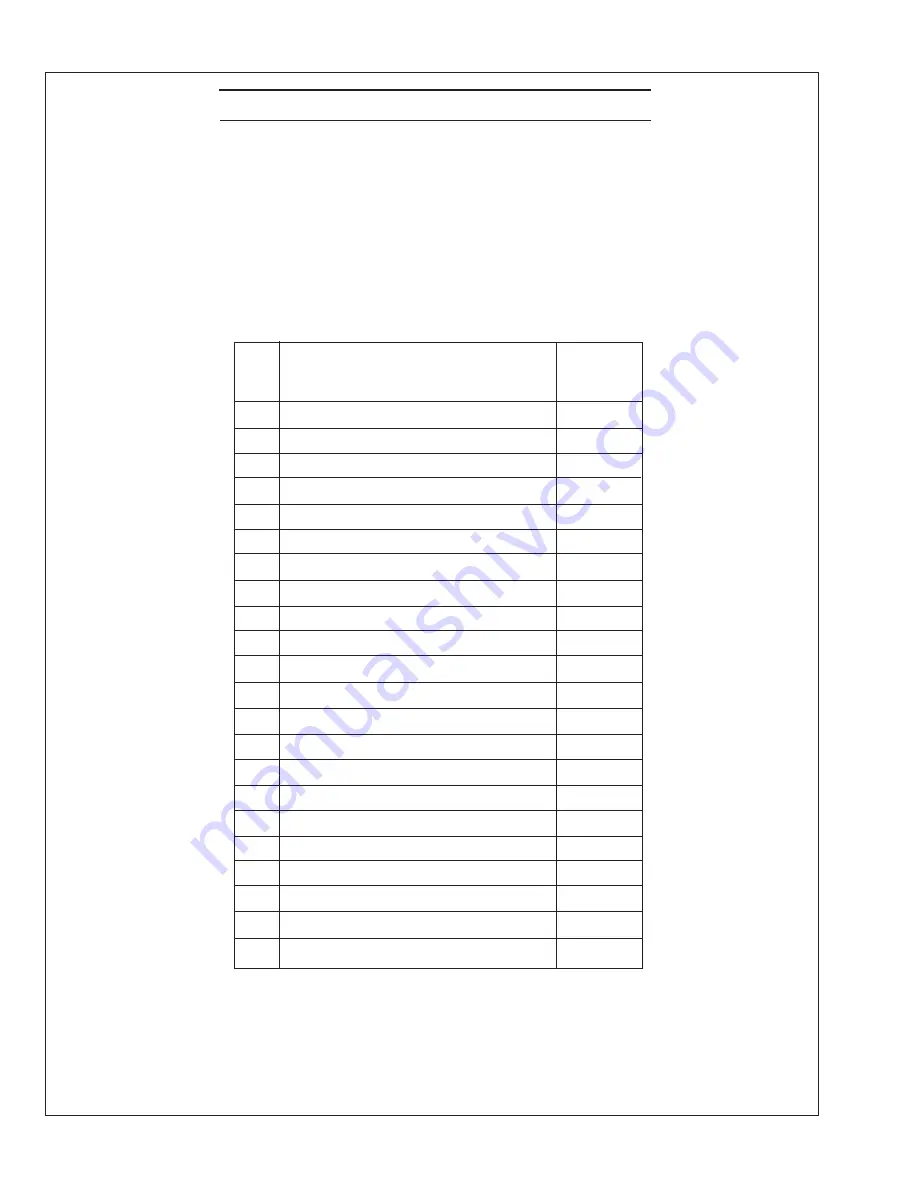
Northern Lights M1064A Operator'S Manual Download Page 54

  OM2-2  1/17

54


Item Description 

Quantity 


    1 

Lube Oil Filter 

    2 

Air  Filter Element 

1

    3 

Fuel Filter 

    4 

Fuel Filter Element 

4  

    5 

Fuel Lift Pump 

1

    6 

Injector 

    7 

Thermostat 

    8 

Thermostat Seal Ring 

    9 

Thermostat Cover Gasket 

1

  10 

Rocker Cover Gasket 

  11 

Engine Overhaul Gasket Kit  

  12 

Zinc Anode*  

  13 

Raw Water Pump Impeller* 

2

  14 

Raw Water Pump Cover Gasket* 

  15 

Raw Water Pump* 

1

  16 

Raw Water Pump Bearing* 

2

  17 

Coolant Pump Repair Kit 

1

  18 

Coolant Pump Gasket 

1

  19 

Drive Belt 

  20 

Workshop Manual 


*Heat exchanger cooled engines only

Safety at sea depends on careful preparation, product knowledge, and having the right 

tools and parts. Below is a list of parts Northern Lights, Inc. recommends you carry 

onboard at all times.

Onboard Parts Kits are available from your dealer. 

We consider these minimum quantities. Your vessel's operating conditions may require 

more of a given part. Consult your dealer.  The example below lists typical items for 

either heat exchanged or keel cooled engines.

On Board Spare Parts

52

Summary of Contents for M1064A

Page 1: ...OPERATOR S MANUAL OM2 2 For Models M1064A M1064D M1064T1 M1064T2 M1066A1 M1066A2 M1066A3 M1066T M40C2 M55C2 M65C2 M99C2...

Page 2: ...d other reproductive harm CALIFORNIA Proposition 65 Warning Northern Lights 4420 14th Avenue N W Seattle WA 98107 Tel 206 789 3880 Fax 206 782 5455 Copyright 2013 Northern Lights Inc All rights reserv...

Page 3: ...il Changes 19 Changing Oil Filter 19 Air Filter 19 Valve Clearances 20 Fuels General 21 Crankshaft Vibration Damper 6 Cyl 22 Fuel Filters 22 23 Bleeding the Fuel System 23 Injector Service 23 25 Injec...

Page 4: ...4045 engine block with a mechanically controlled fuel system M1064D M 1064 or 1066 MP55C2 Northern Lights turbocharged marine generator set with a John Deere Powertech Tier II 4045 engine block with...

Page 5: ...s in good and clean condition Replace missing or damaged signs Be sure new equipment components and repair parts include the current safety signs For replacement signs proper placement of safety signs...

Page 6: ...l moving parts have stopped before making any adjustments connections or performing any other type of service to the engine or other driven equipment Prevent accidental discharge of starting fluids by...

Page 7: ...lyte is poisonous and strong enough to burn skin eat holes into clothing and other materials and cause blindness if splashed into eyes To Avoid Hazards Fill batteries only in well ventilated areas Wea...

Page 8: ...ispose of paint and solvent properly Service Cooling System Safely WARNING Opening a pressurized cooling system can release explosive fluids and causing serious burns Before opening any pressurized co...

Page 9: ...ater source components between the high pressure fuel pump and nozzles on engines with high pressure fuel systems ONLY AUTHORIZED TECHNICIANS CAN PERFORM REPAIRS ON AN HIGH PRESSURE FUEL INJECTION SYS...

Page 10: ...be achieved at the local supply valve shut off valves further back in the system and re check the bleed off point until complete shut off is achieved Affix a DO NOT OPERATE tag to each valve handle th...

Page 11: ...OM2 2 1 17 9 Notes...

Page 12: ...ump 11 Lube Oil Dipstick 12 Lube Oil Filter 13 Optional Hydrolastic Mount 14 Starter 15 Lube Oil Drain 16 Fuel Manifold 17 Expansion Tank 18 Thermostat Cover 19 Heat Exchanger Zincs 20 Heat Exchanger...

Page 13: ...r 12 Wet Exhaust Elbow 13 Exhaust Manifold Drain 14 Electric Starter 15 Engine Block Drain 16 Fuel Injection Pump 17 Heat Exchanger Zinc 2 18 Heat Exchanger Drain 19 Heat Exchanger 20 Raw Water Pump 2...

Page 14: ...ernator 6 Coolant Fill 7 Expansion Tank 8 Belt Guard 9 Coolant Pump 10 Centerbonded Mounts 11 Lube Oil Drain 12 Lube Oil Filter 13 Dipstick 14 Electric Starter 15 Closed Crankcase Vent 16 Exhaust Mani...

Page 15: ...he switch and it will return to RUN position To stop the engine hold the switch in the STOP position 3 OIL PRESSURE GAUGE The oil pressure gauge shows the oil pressure in the engine lubricating system...

Page 16: ...ce is greater than 30 have an electrician balance the load properly This will ensure longer generator life and better economy 1 SHUTDOWN BYPASS SWITCH This switch bypasses the safety shutdown feature...

Page 17: ...the engine at high idle for 1 to 2 minutes before adding load If the stand by generator set is loaded as soon as it reaches rated speed this procedure would not apply Operating 1 Check Gauges Often Oi...

Page 18: ...0 F 93 3 C Repeat the troubleshooting process 3 If the shutdown is activated and the temperature gauge shows temperature within normal temperature range a Check the engine crankcase oil level b If the...

Page 19: ...st if necessary SP12 Check fuel injection pump SP17 Check and clean heat exchanger 1 Change the oil and filter at 50 hours using break in oil again until changing it at 100 hours then at every 250 hou...

Page 20: ...stats SP30 Check aftercooler clean air side 1 Change the oil and filter at 50 hours using break in oil again until changing it at 100 hours then at every 250 hours 2 Perform all maintenance once a yea...

Page 21: ...s been drained into suitable container close valve remove drain hose and replace plug in base frame outlet c Refill engine with recommended oil 4 Engine Lube Oil Capacity depending on oil pan size SP3...

Page 22: ...nut Re adjust as needed Servicing NOTE Firing order is 1 3 4 2 Reproduced by permission of Deere Company c2004 Deere Company All rights reserved RG4776 Figure 10 A Front of Engine B No 1 Piston at TDC...

Page 23: ...gn matter out of fuel b Avoid storing fuel for long periods of time c Fill the fuel tank at the end of each day s operation This will reduce condensation 6 Biodiesel Biodiesel involves the transesteri...

Page 24: ...r pump lever on fuel transfer pump see component locations until most of the air bubbles are expelled and clear fuel escapes the bleed plug Tighten the bleed plug b If the engine will not start it may...

Page 25: ...g on the nozzle body above the carbon stop seal groove This coating will become discolored during normal operation but this is not harmful Do not use a motor driven brush to clean up nozzle body Figur...

Page 26: ...n pump seals are broken by unauthorized persons DB4 AND DB2 INJECTION PUMPS REMOVAL All Stanadyne DB2 and DB4 injection pumps will have a retained drive shaft shaft stays in pump when pump is removed...

Page 27: ...s Pump drive shaft index pin may be damaged if pin is not properly aligned with drive gear key slot and if the nuts are tightened more than three turns 4 Install three flat washers lock washers and he...

Page 28: ...the pump to the front plate to 20 foot lbs 27 N m 11 Connect injection pump pressure lines Figure 23 E Beginning with outlet connection to 1 cylinder Figure 24 B and continue around the pump head in c...

Page 29: ...eded to control liner pitting or erosion rust scale and acidity LINER EROSION PITTING 1 Cylinder liner walls Figure 25 A which are in contact with engine coolant Figure 25 B can be eroded or pitted un...

Page 30: ...in contact with coolant 2 DO NOT use an EGC containing sealer or stop leak additives 3 DO NOT use EGC containing more than 0 1 anhydrous metasilicate This type of concentrate which is intended for use...

Page 31: ...n working on hot engines to avoid burns Allow the engine to cool before working on the cooling system Open the filler cap carefully using protective clothing when the engine is warm 1 Flush the coolin...

Page 32: ...cover using a new gasket Note Make sure there is always an extra impeller and cover gasket in reserve and on board DRIVEN EQUIPMENT Gears and PTO s 1 Manufacturer s service recommendations vary See y...

Page 33: ...ine 4 Remove and clean batteries 5 All engine openings should be sealed with plastic bags and tape 6 Store in a dry protected place To Remove Generator Set from Long Term Storage 1 Take off all protec...

Page 34: ...check injection nozzles Electronic Fuel System problem if equipped See your dealer Injection pump not getting fuel or air in fuel system Check fuel flow at supply pump or bleed fuel system DC ELECTRIC...

Page 35: ...section a Engine Runs Irregularly or Stalls Frequently Below normal engine temperature Remove and check thermostat Clogged primary fuel filter element Clean or replace filter element Clogged secondary...

Page 36: ...el Improper type of oil Drain and fill crankcase with correct oil Partially plugged oil filter Replace filter a High Oil Consumption Break in period Oil consumption decreases after break in Crankcase...

Page 37: ...OM2 2 1 17 35 AC Wiring Diagram A C Wiring All voltages with an APR63 5 Non PMG Drawing B 5689F Revised 4 10 12...

Page 38: ...OM2 2 1 17 36 A C Wiring Diagram A C Wiring All voltages with an AVC63 12B1 PMG Drawing B 7429P Revised 7 9 12...

Page 39: ...OM2 2 1 17 37 A C Wiring Diagram A C Wiring AVR SX460 w Stamford 4 12 wire Drawing B 5073M Added 4 10 12...

Page 40: ...OM2 2 1 17 38 D C Wiring Diagram D C Wiring 12 Volt Standard Ground for M1064D and M1064T1 Drawing C 5453J...

Page 41: ...OM2 2 1 17 39 D C Wiring 12 Volt Standard Ground for M40C2 and M55C2 Drawing C 6916 D C Wiring Diagram Revised 4 10 12...

Page 42: ...OM2 2 1 17 40 D C Wiring Diagram D C Wiring 24 Volt Isolated Ground for M1064D and M1064T1 Drawing C 5759D Revised 4 10 12...

Page 43: ...OM2 2 1 17 41 D C Wiring 24 Volt Isolated Ground for M40C2 M55C2 Drawing C 5623 D C Wiring Diagram...

Page 44: ...OM2 2 1 17 42 D C Wiring 12 Volt Standard Ground for M1064T2 M1064A M1066T and M1066A1 Drawing C 6890 Revised 4 10 12 D C Wiring Diagram...

Page 45: ...OM2 2 1 17 43 D C Wiring Diagram Revised 4 10 12 D C Wiring 12 Volt Standard Ground for M65C2 and M99C2 Drawing C 6878A...

Page 46: ...OM2 2 1 17 44 D C Wiring 24 Volt Isolated Ground for M1064T2 M1064A M1066T M1066A1 Drawing C 6900 Revised 4 10 12 D C Wiring Diagram...

Page 47: ...OM2 2 1 17 45 D C Wiring Diagram D C Wiring 24 Volt Isolated Ground for M65C2 and M99C2 Drawing C 6889A Added 4 10 12...

Page 48: ...OM2 2 1 17 46 Notes Added 4 10 12...

Page 49: ...OM2 2 01 17 47 D C Wiring 12 Volt Standard Ground for M1066A2 and M1066A3 Drawing D 3769B...

Page 50: ...OM2 2 01 17 48 D C Wiring 24 Volt Isolated Ground for M1066A2 and M1066A3 Drawing D 3772C...

Page 51: ...OM2 2 1 17 51 Panel Wiring Diagram S 3B S 3C Panel Wiring Diagram 1224 volt Viewline Drawing A 12638A Added 4 10 12 49...

Page 52: ...OM2 2 1 17 52 Panel Wiring Diagram Added 4 10 12 50 S 1B Panel Wiring Diagram 12 volt Drawing A 3170...

Page 53: ...OM2 2 1 17 53 Panel Wiring Diagram S 1B Panel Wiring Diagram 24 volt Drawing A 4792 Added 4 10 12 51...

Page 54: ...g 2 17 Coolant Pump Repair Kit 1 18 Coolant Pump Gasket 1 19 Drive Belt 1 20 Workshop Manual 1 Heat exchanger cooled engines only Safety at sea depends on careful preparation product knowledge and hav...

Page 55: ......

Page 56: ......

Page 57: ...4420 14th Ave NW Seattle WA 98107 Tel 206 789 3880 1 800 762 0165 www northern lights com Northern Lights and Lugger are registered trademarks of Northern Lights Inc 2017 All rights reserved Litho USA...

Reviews: