background image

Connecting Alarms

296-1011-202 Rel. 5.0, Doc. Rev. 02.01

2-5

Chassis Connections

Reference

For pinout assignments, see 

Appendix A, “Technical Specifications.”
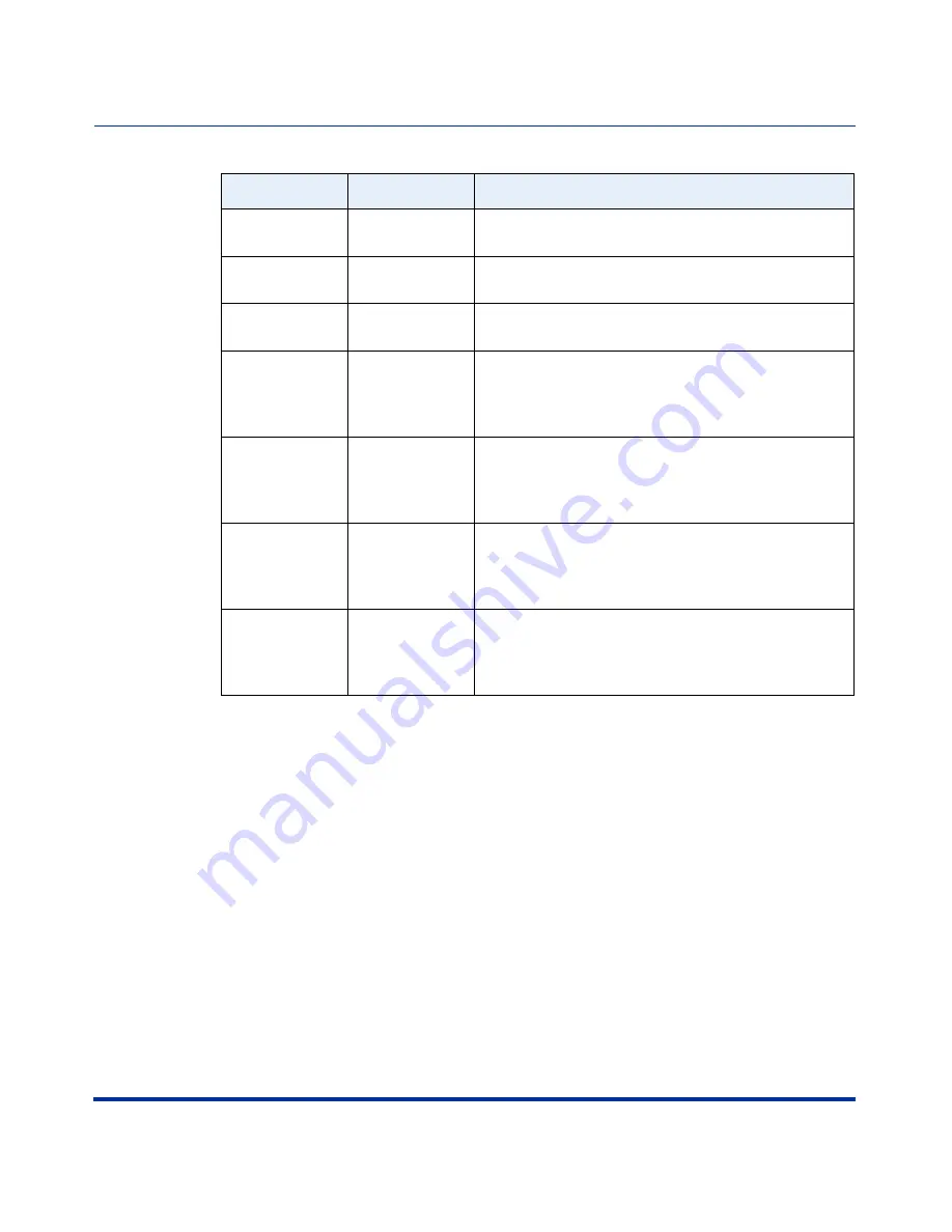
ATM PVPC 
PVCC Up

Minor

The PVPC/PVCC has been successfully created.

ATM PVPC 
PVCC 

Minor

The PVPC/PVCC is down.

ATM APS 
Switchover

Minor

A link failure caused the PHY driver to turn on the 
redundant PHY.

Sonet/SDH 
Alarm Sdber

Major

The specified STM-1 is in Signal Degrade Bit Error 
Rate alarm. The value set in the 
SigDegradeThreshold attribute for this line has 
been exceeded.

Sonet/SDH 
Alarm Sfber

Major

The specified STM-1 is in Signal Failure Bit Error 
Rate alarm. The value set in the 
SigFailureThreshold attribute for this line has been 
exceeded.

Sonet/SDH 
Alarm Sdber 
Clear

Major

The specified STM-1 is not in Signal Degrade Bit 
Error Rate alarm. The Signal Degrade Bit Error Rate 
is now below the SigDegradeThreshold value set in 
the configuration.

Sonet/SDH 
Alarm Sfber 
Clear

Major

The specified STM-1 is not in Signal Failure Bit Error 
Rate alarm. The Signal Failure Bit Error Rate is now 
below the SigFailureThreshold value set in the 
configuration.

Alarm Type

Severity

Description

Summary of Contents for CVX 600

Page 1: ...296 1011 202 Document Revision 02 01 CVX Multi Service Access Switch Release 5 0 August 2001 CVX 600 Multi Service Access Switch Hardware Installation Guide...

Page 2: ...demarks of Nortel Networks All other trademarks are the property of their owners 2001 Nortel Networks All rights reserved Information in this document is subject to change without notice Nortel Networ...

Page 3: ...is no guarantee that interference will not occur in a particular installation If this equipment does cause harmful interference to radio or television reception which can be determined by turning the...

Page 4: ...rical Business equipment and Canadian Standards Association CAN CSA C22 2 No 950 95 Third Edition Australian Requirements N441 The regulator for telecommunications and radio communications in Australi...

Page 5: ...ons du service de t l communications local L appareillage doit aussi tre raccord selon des m thodes accept es Les r parations de l appareillage certifi devraient tre confi es un service d sign par le...

Page 6: ...the Voluntary Control Council for Interference by Data Processing Equipment and Electronic Office Machines that are aimed at preventing radio interference in commercial and or industrial areas Consequ...

Page 7: ...c Code ANSI NFPA 70 The DC power source must be isolated from the AC power source and must have a proper ground The grounded conductor of the DC supply circuit can be connected to the frame grounding...

Page 8: ...with the same or equivalent type recommended by the manufacturer Discard used batteries according to the manufacturer s instructions Attention Il y a danger d explosion s il y a remplacement incorrect...

Page 9: ...s Only vi Safety Warnings vii General Warnings vii DC Power Supply Warnings vii Lithium Battery Caution viii Preface About This Guide xv Introduction xv Topics xv Chapters and Appendixes in This Guide...

Page 10: ...5 Overview 1 5 Reference 1 5 Mounting Options 1 5 Mounting the CVX 600 in a Rack 1 7 Rack Capacity 1 7 Rack Requirements 1 7 Nortel Networks Rack Recommendation 1 7 Rack Placement 1 7 Ceiling Require...

Page 11: ...is Installation 1 22 Installing the Chassis 1 23 Chapter 2 Chassis Connections About This Chapter 2 1 Introduction 2 1 Topics 2 1 Connecting Alarms 2 2 Introduction 2 2 Alarm Categories 2 2 Alarm Type...

Page 12: ...ble Mounts 2 27 Routing Fiber Optic Cables 2 28 Installing and Removing the Flash Memory Cards 2 29 Description 2 29 Reference 2 29 Inserting a Flash Memory Card 2 30 Removing a Flash Memory Card 2 31...

Page 13: ...istatic Wrist Strap 3 2 Location of Wrist Strap 3 2 Purpose of Wrist Strap 3 2 How to Attach the Wrist Strap 3 2 Replacing Modules and Filler Panels 3 4 Introduction 3 4 Removing and Installing Filler...

Page 14: ...vironmental Specifications A 3 Specifications A 3 Cooling Requirements A 4 Need for Ventilation A 4 Methods of Cooling A 4 Airflow A 4 Electromagnetic Emissions and Radio Frequency A 5 CVX 600 Require...

Page 15: ...Parts Needed A 14 Pin Data A 14 Audible and Visual Alarm Interface Specifications A 16 Alarm Interface Connector A 16 Signals A 16 Reference A 16 Power Specifications A 17 Power Options A 17 AC Power...

Page 16: ......

Page 17: ...installation procedures vary between Telco and ISP customers use this manual as a guide for installation Topics This preface covers the following topics Topic Page Chapters and Appendixes in This Guid...

Page 18: ...CVX 600 Hardware Installation Guide Chapters and Appendixes in This Guide This guide contains the following chapters and appendixes For Go to Chassis Installation Chapter 1 Chassis Connections Chapter...

Page 19: ...on contact your Nortel Networks account representative Accessing Software Upgrades Software upgrades are accessible online through the World Wide Web at http www nortelnetworks com Click Customer Supp...

Page 20: ...completed In addition contact Technical Support as instructed in the previous section so that arrangements can be made for replacement equipment Do not return any part of the shipment until you receiv...

Page 21: ...describes how to install the CVX 600 chassis Topics This chapter covers the following topics Topic Page CVX 600 Chassis Overview 1 2 Preparing the Site for the Installation 1 5 Mounting the CVX 600 i...

Page 22: ...ntrol cards SCCs Remote Access Configuration The CVX 600 chassis configured for remote access is equipped with the following An internal fan module for system cooling A redundant DC power interface An...

Page 23: ...s Two slots for primary and redundant system control cards SCCs SCC SCC SCC SCC SEC PRI System Pwr Good Fail Redun 10 100 Enet 3 2 1 HSSI RESET PCMCIA 1 2 System Pwr Good Fail Redun 10 100 Enet 3 2 1...

Page 24: ...S3 E 1 x 12 DS1 x 12 Tx Rx 10 100 Enet HSSI Clock Clock 12 11 10 9 8 7 12 11 10 9 6 5 4 8 7 6 5 3 2 1 4 3 2 1 AC chassis option shown CVX 0219B Grounding lugs screw our slots or line ermination odules...

Page 25: ...nstallation of the rack if used tools and equipment needed space requirements and weight These issues are addressed in detail in this chapter Reference For information about the environmental requirem...

Page 26: ...tem Power Good Failed Redun Ethernet HSSI 1 3 2 1 Reset PCMCIA 1 2 System Power Good Failed Redun Ethernet HSSI 1 3 2 1 Reset PCMCIA 1 2 DS1 Yellow Red 1 2 3 4 5 6 7 8 9 10 11 12 Power Good Failed Red...

Page 27: ...rks Rack Recommendation Nortel Networks recommends using a Physical Telecommunications Environment PTE 2000 rack Rack Placement The rack you plan to install should be in an area that is A dedicated eq...

Page 28: ...tions Before you install the rack at your site make sure that the equipment room can accommodate the size and weight of the rack and the CVX 600 To determine the total weight add the weight of all of...

Page 29: ...ic protection The following table describes each of the anchor kits Note You must use six floor anchors to secure the PTE 2000 rack to the equipment room floor Kit Number Earthquake Zone Compliance Fl...

Page 30: ...s on a bare concrete floor you must drill to the following depths 2 in 51 mm for the 3 8 in anchor for zone 2 earthquake compliance NTRU0323 NTRU0326 4 in 103 mm for the M12 anchor for zone 4 earthqua...

Page 31: ...ack is approximately 125 lb 57 kg excluding the shipping crate Use freight elevators if available to move the equipment to upper floors Rack Cooling Requirements You can install up to seven AC powered...

Page 32: ...on contains two independent power modules If one module fails the other module powers the CVX 600 AC PM AC PM Fans 1 2 3 4 5 6 CVX 6oo BIP BIP AC PM 1 AC PM 2 PDU 2 PDU 1 ESD Jack O I O I AC Chassis O...

Page 33: ...wer source Note Both versions contain internal circuit breaker modules Fans 1 2 3 4 5 6 CVX 6oo BIP BIP PDU 2 PDU 1 ESD Jack O I O I DC Chassis Option CVX 0238B SCC SCC System Pwr Good Fail Redun 10 1...

Page 34: ...ed You have the proper equipment and tools You have network lines available Unpacking the Shipment The CVX 600 is secured to a pallet and covered by a box to protect the contents during shipment Move...

Page 35: ...s that secure the chassis to the pallet brackets 6 Using a 9 16 inch wrench remove the four bolts that secure the pallet brackets to the pallet 7 Remove the four pallet brackets from the pallet 8 Care...

Page 36: ...Cables and Cable Ties The shipment does not include the cables required for the telephone side of your network Ensure that the installation site has the proper network cabling Cable ties are needed t...

Page 37: ...ations listed in Rack Requirements on page 1 7 If the rack does not have threaded rail holes you must use cagenuts and cagenut screws not supplied Note Before you turn on the CVX 600 you should connec...

Page 38: ...he CVX 600 in one of two ways Position the chassis on a flat sturdy horizontal surface Mount the chassis in a rack Positioning the Chassis on a Flat Surface When positioning the chassis on a flat stur...

Page 39: ...the feet to the four holes in the bottom of the chassis near the corners AC PM AC PM Fans 2 6 CVX 6oo BIP BIP Fille r Sys tem Power Good Failed Redun Eth ern et HSS I 1 3 2 1 Res et PC MC IA 1 2 Sys t...

Page 40: ...cks with front or rear doors or side panels The operating environment must provide airflow at 200 cubic feet per minute CFM per CVX 600 chassis at a temperature range of 32 to 104 F 0 to 40 C The opti...

Page 41: ...es and 0 625 inch spacing between the dual mounting hole pairs The following figure shows the positions on the mounting flange that you use for Telco and EIA racks Note Before you install the CVX 600...

Page 42: ...mplete the chassis installation you need the following hardware Four for DC chassis option or eight for AC chassis option truss head mounting screws included in the shipment Phillips 2 screwdriver Cau...

Page 43: ...to properly align the positions on the mounting flanges with the mounting holes on the rack continued AC PM AC PM Fans 1 2 3 4 5 6 CVX 6oo BIP BIP Filler System Power Good Failed Redun Ethernet HSSI...

Page 44: ...ten the provided hex head screws to 75 in lb using a torque regulating ratchet Nortel Networks cannot recommend a specific torque value for other racks Step Action AC PM AC PM Fans 1 2 3 4 5 6 CVX 6oo...

Page 45: ...he CVX 600 Topics This chapter covers the following topics Topic Page Connecting Alarms 2 2 Connecting Network Cables 2 7 Connecting Power to the Chassis 2 16 Routing the Cables 2 27 Installing and Re...

Page 46: ...s remain open If a failure occurs the contacts close and trigger the connected alarm Alarm Categories The following table lists the three general categories of alarms and the possible causes Warning T...

Page 47: ...operation CVXView generates this alarm Although the raising trap is generated on the CVX 600 it does not recognize this as an alarm condition This alarm must be cleared manually on CVXView Clear Alar...

Page 48: ...ptical interface is up but is in standby mode APS Down Minor The designated optical interface is down ATM Red Alarm Major The specified link port has a critical alarm such as the absence of a line sig...

Page 49: ...gradeThreshold attribute for this line has been exceeded Sonet SDH Alarm Sfber Major The specified STM 1 is in Signal Failure Bit Error Rate alarm The value set in the SigFailureThreshold attribute fo...

Page 50: ...ately 1 2 inch of insulation from the wires 4 Insert the wires into the terminals and tighten the screws to 1 to 2 in lb using a 1 16 inch flat tip screwdriver 5 Connect the other end of the wires to...

Page 51: ...Network Cables Overview You will need to attach network cables to the following CVX 600 interfaces 10 100BASE T on the SCC LTM and SCC RLTM DS1 T1 RJ 45 48C E1 RJ 45 48C DS3 HSSI Optical OC3 STM1 Ref...

Page 52: ...Alarm s Audib le Crit Ret Maj Ret Min Ret Crit Ret Maj Ret Min Ret HSSI 2 Visua l Alarm s Audib le Crit Ret Maj Ret Min Ret Crit Ret Maj Ret Min Ret RX Link 10 100 Enet 1 RX Link 10 100 Enet 3 RX Lin...

Page 53: ...ice To connect T1 cables to the T1 ports and to connect the DS1 DAC LTM to an external clocking device follow this step Step Action 1 Plug the connectors into the receptacles Connect to the telephone...

Page 54: ...s into the receptacles Note Using shielded cabling is an electromagnetic interference EMI requirement for CVX 600 E1 network configurations Note For UK installations using 75 ohm E1 coax a balun is ne...

Page 55: ...n the SCC or DAC Connect to the telephone network CVX 0200A 2xDS3 DAC RLTM 2xDS3 DAC LTM DS3 DAC RLTM DS3 DAC LTM 2xDS3 SCC RLTM Connect to the external clocking device if used DS3 Tx Rx Clock Ref DS3...

Page 56: ...he SCC HSSI RLTM contains one HSSI 50 pin interface receptacle To connect a HSSI cable follow this step Step Action 1 Plug the cable connector into the HSSI interface receptacle Connect the other end...

Page 57: ...of Laser Products Class 1 lasers are considered eye safe however follow these appropriate safety measures Always make sure that the CVX switch is powered down before connecting or disconnecting any op...

Page 58: ...n 1 Remove the rubber plugs from each pair of ports STMx2 CVX 0139D Optical DAC LTM A A A B A B B B Tx Rx Tx Rx Tx Rx Tx Rx 2 1 CLASS 1 LASER PRODUCT APPAXXX A LASER DE CLASSE 1 Optical SCC II LTM Sys...

Page 59: ...p Action CVX 0138B Remove cover Remove covers CVX 0140D Optical DAC LTM Connect to the external clocking device if used Connect to the optical port Tab Optical SCC II LTM Connect to the optical port T...

Page 60: ...ications for information on the torque requirements for securing power and ground cables Make sure the switches on both circuit breaker modules PDUs are off o Read the Safety Warnings on page vii Fans...

Page 61: ...l connector posts Use the compression terminal Note In addition to the grounding location shown in the following sections the AC chassis option also contains an identical grounding location in the upp...

Page 62: ...so contains an identical grounding location in the upper right corner of the rear of the chassis Either location may be used Step Action 1 Locate a suitable ground cable at your facility 2 On the back...

Page 63: ...of the ground cable is properly connected for frame grounding Note In addition to the grounding location shown in the following section the AC chassis option also contains an identical grounding locat...

Page 64: ...and the back of the connector If the screw comes in contact with the wire remove the wire and insert it below the retainer to ensure a proper ground connection 6 Use the flat tip screwdriver to tight...

Page 65: ...ource is only for the DC chassis option Prerequisites Before connecting the CVX 600 to a DC power source see DC Power Supply Warnings on page vii Caution Ensure that the wire gauge you use is adequate...

Page 66: ...odem ISDN Pwr Good Fail Redun Modem ISDN Pwr Good Fail Redun Modem ISDN Pwr Good Fail Redun DAC DS1x24 Pwr Good Fail Redun YEL RED YEL RED 3 1 10 11 24 2 12 22 23 21 19 20 18 16 17 15 13 14 9 7 8 6 4...

Page 67: ...driver 6 Secure the cables using a cable tie through the cable mount on the lower right side of the chassis continued Step Action CVX 0204A 1 2 3 4 5 6 System Controller only 1 2 3 4 5 6 Main Chassis...

Page 68: ...6 in lb 8 Connect the 48V and RETURN DC power cables to the DC power source Step Action CVX 0205A 1 2 3 4 5 6 System Controller only 1 2 3 4 5 6 Main Chassis DC PM 2 DC PM 1 DS3 E 1 x 12 DS1 x 12 Tx...

Page 69: ...ke sure that the two power switches on the circuit breaker modules PDUs are off continued AC PM AC PM Fans 1 2 3 4 5 6 CVX 6oo BIP BIP Filler System Power Good Failed Redun Ethernet HSSI 1 3 2 1 Reset...

Page 70: ...le Step Action AC PM 1 AC PM 2 1 2 3 4 5 6 System Controller only 1 2 3 4 5 6 Main Chassis DC PM 2 DC PM 1 DS3 E 1 x 12 DS1 x 12 Tx Rx Clock Clock 12 11 10 9 8 7 12 11 10 9 6 5 4 8 7 6 5 3 2 1 4 3 2 1...

Page 71: ...Typically the cable mounts on the left are used to route communications cables while the one on the lower right is used to route power cables Locations of Cable Mounts The following figure shows the l...

Page 72: ...sis a rack mounted bracket may be used to support the fiber optic cable Nortel does not supply a bracket for this purpose Securing and Wrapping Fiber Optic Cables Fiber optic cables can be secured wit...

Page 73: ...abeled 1 and 2 Slot 1 is the C drive and slot 2 is the D drive Always use slot 1 for the flash memory card Use slot 2 if you need to copy the flash memory card in slot 1 to a flash memory card in slot...

Page 74: ...y Card To insert a flash memory card follow these steps Step Action 1 Position the card so that its label is facing up 2 Insert the card into slot 1 and gently push the card until it clicks into posit...

Page 75: ...hese steps Step Action 1 Press the eject button next to the slot labeled 1 or 2 from which you want to remove a flash memory card 2 Pull the flash memory card out of the slot System Pwr Good Fail Redu...

Page 76: ...duction You can connect a terminal PC modem or terminal server to the CVX 600 using the console port on the SCC The following procedures provide steps for connecting each piece of equipment Connecting...

Page 77: ...cable follow these steps Step Action 1 Turn on the terminal then configure it using the parameters listed below Reference For instructions see the documentation for the terminal or the terminal emula...

Page 78: ...p Action AC PM 1 AC PM 2 1 2 3 4 5 6 System Controller only 1 2 3 4 5 6 Main Chassis PDU 2 DC INPUT B DS3 E 1 x 12 DS1 x 12 Tx Rx 10 100 Enet HSSI Clock Clock 12 11 10 9 8 7 12 11 10 9 6 5 4 8 7 6 5 3...

Page 79: ...cable to the Console port continued AC PM 1 AC PM 2 1 2 3 4 5 6 System Controller only 1 2 3 4 5 6 Main Chassis PDU 2 DC INPUT B DS3 E 1 x 12 DS1 x 12 Tx Rx 10 100 Enet HSSI Clock Clock 12 11 10 9 8 7...

Page 80: ...Port 2 36 296 1011 202 Rel 5 0 Doc Rev 02 01 CVX 600 Hardware Installation Guide 2 Connect the 9 pin plug end of the console cable to the DB 9 port on the back of the PC Step Action CVX 0120B DB 9 to...

Page 81: ...the documentation for the modem Modem Parameter Value State Baud rate 56 Kb s or less Auto answer Set to n rings with DTR active The value n must be greater than 0 If the value is 0 Auto answer is di...

Page 82: ...using the DB 9 to DB 25 modem cable or through a terminal server Step Action AC PM 1 AC PM 2 1 2 3 4 5 6 System Controller only 1 2 3 4 5 6 Main Chassis PDU 2 DC INPUT B DS3 E 1 x 12 DS1 x 12 Tx Rx 10...

Page 83: ...Yellow Red 1 2 3 4 5 6 7 8 9 10 11 12 Power Good Failed Redun Modem ISDN Power Good Failed Redun Power Good Failed Redun Fans Filler Modem ISDN Power Good Failed Redun Power Good Failed Redun Filler...

Page 84: ...t Maj Ret Min Ret Crit Ret Maj Ret Min Ret 10 100 Enet 10 100 Enet OC3 A RX TX RX TX CLASS 1 LASER PRODUCT APPAXXX A LASER DE CLASSE 1 OC3 A System OC3 Console 10 100 Enet 2 3 Link RX Link RX Link RX...

Page 85: ...gure shows connecting a remote PC to the Ethernet port Note The 10 100 Mb s Ethernet port is an autosensing port that adjusts automatically for 10 or 100 Mb s transmission This means that the port sel...

Page 86: ...on the circuit breakers PDUs are off 5 Apply power from the power source 6 Ensure that the red LEDs on both PDUs are on If they are turn the switches on both circuit breakers PDUs on If the LEDs are...

Page 87: ...ng the LEDs Introduction The LEDs provide important information about the operating status of the system control and access cards These include the following cards SCC SM SCC RLTM Ethernet 10 100 Mb s...

Page 88: ...have However the LED information is the same SCC RLTM SCC SM CVX 0209C System Redundant HSSI 2 Visu al Alar ms Audi ble Crit Ret Maj Ret Min Ret Crit Ret Maj Ret Min Ret RX Link 10 100 Enet 1 RX Link...

Page 89: ...n green Off Flashing green Successful system boot no errors detected No power failure detected or on standby Code loading during system boot Fail Off On red No power Failure detected Redun Off On gree...

Page 90: ...RLTM SCC RLTM SCC SM CVX 0210B HSSI 2 RX Link 10 100 Enet 1 RX Link 10 100 Enet 3 RX Link 10 100 Enet Visu al Alar ms Audi ble Crit Ret Maj Ret Min Ret Crit Ret Maj Ret Min Ret Console System Pwr Goo...

Page 91: ...en Successful system boot no errors detected No power failure detected or on standby Code loading during system boot Fail Off On red No power Failure detected Redun Off On green No power or no redunda...

Page 92: ...cal SCC II SM Visual Alarms Audible Crit Ret Maj Min Ret Ret Crit Ret Maj Min Ret Ret Link RX Link RX Link RX OC3 STM1 2 OC3 STM1 1 RX RX TX TX 2 3 1 10 100 Enet System Pwr Good Fail Redun 10 100 Enet...

Page 93: ...en On red Normal operating condition Sonet SDH alarm condition ATM Off On red On green Not initialized Initialized but not operational Operational Prot Off On amber Automatic protection switching is e...

Page 94: ...01 CVX 600 Hardware Installation Guide LEDs on the Optical SCC II LTM The following table describes the LEDs on the Optical SCC II LTM LED State Meaning Link Off No link present On green Link present...

Page 95: ...detected or on standby Flashing green Code loading during system boot Fail Off No power On red Failure detected Redun Off No power or no redundancy On green A working redundant configuration LOF Off...

Page 96: ...Pwr Good Fail Redun YEL RED YEL RED 3 1 10 11 24 2 12 22 23 21 19 20 18 16 17 15 13 14 9 7 8 6 4 5 DAC DS1x12 Pwr Good Fail Redun YEL RED 3 1 10 11 2 12 9 7 8 6 4 5 DAC E1x12 Pwr Good Fail Redun YEL R...

Page 97: ...uccessful system boot no errors detected No power failure detected or on standby Fail Off On red No power Failure detected Redun Off On green No power or redundancy A working redundant configuration Y...

Page 98: ...ating and editing the system configuration at boot time see the manual CVX Multi Service Access Switch Startup Guide LED State Meaning Pwr Off On green Power off Power on Good On green Off Successful...

Page 99: ...the following topics Topic Page Attaching the Antistatic Wrist Strap 3 2 Replacing Modules and Filler Panels 3 4 Removing and Installing Filler Panels 3 4 Replacing the SCC SM 3 11 Replacing the SCC L...

Page 100: ...trap The antistatic wrist strap directs the discharge of static electricity from your body to the chassis thereby protecting sensitive electronic components How to Attach the Wrist Strap Follow these...

Page 101: ...ist then adjust it to ensure that the metal buckle inside the strap touches your skin 4 Plug the jack at the other end of the cable into the front or rear of the chassis depending on which side of the...

Page 102: ...M Replace the SCC LTM or SCC RLTM Replace other service modules SMs Replace DAC LTMs and DAC RLTMs Removing and Installing Filler Panels You must install filler panels in any empty slots at the front...

Page 103: ...ws on the left and right sides of the panel 2 Remove the filler panel CVX 0211A AC PM 1 AC PM 2 1 2 3 4 5 6 System Controller only 1 2 3 4 5 6 Main Chassis PDU 2 DC INPUT B DS3 E 1 x 12 DS1 x 12 Tx Rx...

Page 104: ...pes of fillers Step Action 1 Insert the filler panel into the empty slot 2 Use a 1 4 inch flat tip screwdriver to tighten the screws to 5 in lb by turning them clockwise SCC LTM Filler MAC DAC LTM Fil...

Page 105: ...CVX 0145A Unlocked position Filler CVX 0146C Open ejectors AC PM AC PM Fans 1 2 3 4 5 6 CVX 6oo BIP BIP Power Good Failed Redun Ethernet HSSI 1 3 2 1 Power Good Failed Redun Ethernet HSSI 1 3 2 1 DS1...

Page 106: ...talling a Front Filler Panel To install a front filler panel follow these steps Note Filler panels for slots 1 to 4 are marked Filler and filler panels for slots 5 and 6 are marked System Filler Step...

Page 107: ...ts 2 Ensure that the ejectors are extended at an angle but not all of the way Caution Extending the ejectors all of the way may result in ejector breakage when attempting to close them in step 4 conti...

Page 108: ...ckwise Step Action CVX 0148C AC PM AC PM Fans 1 2 3 4 5 6 CVX 6oo BIP BIP Power Good Failed Redun Ethernet HSSI 1 3 2 1 Reset Power Good Failed Redun Ethernet HSSI 1 3 2 1 Reset Power Good Failed Redu...

Page 109: ...will need to shut down the CVX switch to replace the SCC SM Reference See the manual CVX Multi Service Access Switch Configuration Guide for information about editing and managing configuration files...

Page 110: ...To remove the SCC SM follow these steps Step Action 1 Remove the flash memory card from the PCMCIA slot by pressing the eject button located next to the slot 2 Using a flat tip screwdriver turn the l...

Page 111: ...50C Open ejectors System Pwr Good Fail Redun 3 2 1 RESET PCMCIA 1 2 AC PM AC PM Fans 1 2 3 4 5 6 CVX 6oo BIP BIP System Power Good Failed Redun Ethernet HSSI 1 3 2 1 Reset PCMCIA 1 2 AC PM 1 AC PM 2 P...

Page 112: ...1 Make sure that the locking screw is in the unlocked position slot is horizontal 2 Ensure that the ejectors are extended at an angle but not all of the way Caution Extending the ejectors all of the w...

Page 113: ...upper SCC SM 7 Observe the LEDs on the SCC SM to verify proper operation Step Action AC PM AC PM Fans 1 2 3 4 5 6 CVX 6oo BIP BIP System Power Good Failed Redun Ethernet HSSI 1 3 2 1 Reset PCMCIA 1 2...

Page 114: ...ports You will need to reinstall this cabling on the replacement SCC LTM RLTM Removing the SCC LTM or SCC RLTM To remove the SCC LTM or SCC RLTM follow these steps Caution Before removing the SCC LTM...

Page 115: ...p Action CVX 0154B 3 4 5 6 System Controller only 1 2 3 4 Main Chassis DS3 E 1 x 12 DS1 x 12 Clock Clock 12 11 10 9 8 7 12 11 10 9 6 5 4 8 7 6 5 3 2 1 4 3 2 1 5 6 4 5 6 System Controller only System R...

Page 116: ...de the module out of the chassis 6 Place the module in an antistatic bag or on an antistatic work surface Step Action CVX 0155B 3 4 5 6 System Controller only 1 2 3 4 Main Chassis DS3 E 1 x 12 DS1 x 1...

Page 117: ...levers and push them outward then push the SCC LTM RLTM into the chassis until its connector touches the connector on the SCC SM 4 Push the levers inward to fully engage the locking mechanism continue...

Page 118: ...on the SCC LTM RLTM you just removed 7 Turn the power back on by turning on the switches on the PDUs 8 Observe the LEDs on the SCC LTM RLTM to verify proper operation Step Action CVX 0157C 3 4 5 6 Sys...

Page 119: ...e same LTM These service modules can occupy chassis slots 1 to 4 Replacement Procedure The procedure for replacing these service modules is the same as the procedure for replacing the SCC SM Reference...

Page 120: ...teps Step Action 1 Using a 1 4 inch flat tip screwdriver turn the locking screw in the upper left corner of the filler panel 1 4 turn counterclockwise 2 Grasp the left and right ejector levers and pus...

Page 121: ...1 2 3 4 5 6 CVX 6oo BIP BIP System Power Good Failed Redun Ethernet HSSI 1 3 2 1 Reset PCMCIA 1 2 System Power Good Failed Redun Ethernet HSSI 1 3 2 1 Reset PCMCIA 1 2 DS1 Yellow Red 1 2 3 4 5 6 7 8 9...

Page 122: ...Action 1 Make sure that the locking screw is in the unlocked position slot horizontal 2 Ensure that the ejectors are extended at an angle but not all of the way Caution Extending the ejectors all of...

Page 123: ...in 5 Using a 1 4 inch flat tip screwdriver turn the locking screw 1 4 turn clockwise 6 Observe the LEDs on the MAC or DAC SM to verify proper operation Step Action AC PM AC PM Fans 1 2 3 4 5 6 CVX 6o...

Page 124: ...configuration of installed network cabling before you disconnect any cables You will need to reinstall this cabling on the replacement LTM References For more information on removing the service modu...

Page 125: ...flat tip screwdriver to loosen the locking screws continued 3 CVX 0162C 3 4 5 6 System Controller only 1 2 3 4 Main Chassis DS3 E 1 x 12 DS1 x 12 Clock Clock 12 11 10 9 8 7 12 11 10 9 6 5 4 8 7 6 5 3...

Page 126: ...Place the module in an antistatic bag or on an antistatic work surface Step Action 3 CVX 0163C 3 4 5 6 System Controller only 1 2 3 4 Main Chassis DS3 E 1 x 12 DS1 x 12 Clock Clock 12 11 10 9 8 7 12 1...

Page 127: ...h the LTM or RLTM into the chassis until its connector touches the connector on the service module 3 Push the levers inward to fully engage the locking mechanism continued 3 CVX 0164C 3 4 5 6 System C...

Page 128: ...k cabling and alarm wiring used on the LTM or RLTM you just removed 6 Observe the LEDs on the service module to verify proper operation Step Action 3 CVX 0165B 3 4 5 6 System Controller only 1 2 3 4 M...

Page 129: ...fan module contains two fans and is located on the left side of the chassis Caution A malfunctioning fan module can cause the entire chassis to overheat This condition can lead to system and network...

Page 130: ...unterclockwise to unlock AC PM AC PM CVX 6oo BIP BIP AC PM 1 AC PM 2 PDU 2 ESD Jack O I O I CVX 0166B Fans 1 2 3 4 5 6 PDU 1 Fans Fans Locked Unlocked Unlock Modem ISDN Pwr Good Fail Redun DAC DS1x12...

Page 131: ...sis Be careful not to place your hands or fingers near the fan blades 3 Slide the fan module out of the chassis AC PM AC PM CVX 6oo BIP BIP AC PM 1 AC PM 2 PDU 2 ESD Jack O I O I CVX 0167B Fans 1 2 3...

Page 132: ...0 Doc Rev 02 01 CVX 600 Hardware Installation Guide Installing a Fan Module To install a fan module follow these steps Step Action 1 Make sure that the locking screws are in the unlocked position slot...

Page 133: ...flat tip screwdriver turn the locking screws 1 4 turn clockwise 5 Verify that the replacement fan module is operating properly The green LED should be on and air should be exiting the chassis vents St...

Page 134: ...ure that the switch is turned off 2 Using a flat tip screwdriver turn the locking screw 1 4 turn counterclockwise to unlock AC PM AC PM Fans 1 2 3 4 5 6 CVX 6oo BIP BIP AC PM 1 AC PM 2 PDU 2 PDU 1 ESD...

Page 135: ...he chassis Step Action AC PM AC PM Fans 1 2 3 4 5 6 CVX 6oo BIP Filler AC PM 1 AC PM 2 PDU 2 PDU 1 ESD Jack O I CVX 0171B Modem ISDN Pwr Good Fail Redun DAC DS1x12 Pwr Good Fail Redun YEL RED 3 1 10 1...

Page 136: ...le s front panel until you feel the module connect to the chassis connector The front panel of the PDU module should be flush with the front of the chassis CVX 0172A BIP Locked BIP Unlocked AC PM AC P...

Page 137: ...LED comes on Step Action AC PM AC PM Fans 1 2 3 4 5 6 CVX 6oo BIP AC PM 1 AC PM 2 PDU 2 PDU 1 ESD Jack O I CVX 0174B BIP O I BIP Locked BIP Unlocked Modem ISDN Pwr Good Fail Redun DAC DS1x12 Pwr Good...

Page 138: ...wise AC PM AC PM Fans 1 2 3 4 5 6 CVX 6oo BIP BIP Power Good Failed Redun Ethernet 1 3 2 Power Good Failed Redun Ethernet 1 3 2 Yellow Red 1 2 3 4 5 6 7 8 9 10 11 12 Power Good Failed Redun Power Good...

Page 139: ...HSSI 1 3 2 1 Power Good Failed Redun Ethernet HSSI 1 3 2 1 Yellow Red 1 2 3 4 5 6 7 8 9 10 11 12 Power Good Failed Redun Power Good Failed Redun Power Good Failed Redun AC PM 1 AC PM 2 PDU 2 PDU 1 ESD...

Page 140: ...front panel of the power module should be flush with the front of the chassis AC PM Fans 1 2 3 4 5 6 CVX 6oo BIP BIP Power Good Failed Redun Ethernet HSSI 1 3 2 1 Power Good Failed Redun Ethernet HSS...

Page 141: ...HSSI 1 3 2 1 Reset Yellow Red 1 2 3 4 5 6 7 8 9 10 11 12 Power Good Failed Redun Power Good Failed Redun Power Good Failed Redun AC PM 1 AC PM 2 PDU 2 PDU 1 ESD Jack O I O I CVX 0217B CVX 6oo BIP AC P...

Page 142: ...Doc Rev 02 01 CVX 600 Hardware Installation Guide Ordering Replacement Components How to Order If necessary you can order CVX 600 replacement components from Nortel Networks See Customer Services on p...

Page 143: ...the following topics Topic Page Chassis Specifications and Clearances A 2 Environmental Specifications A 3 Cooling Requirements A 4 Electromagnetic Emissions and Radio Frequency A 5 Cable Specificati...

Page 144: ...ensure proper airflow for cooling The following table lists the minimum clearance requirements for the CVX 600 chassis Attribute Measurement Height with AC module Height without AC module 10 5 in 26...

Page 145: ...ment Operating temperature 23 to 104 F 5 to 40 C stable 5 C is for short term operation only Operating altitude 0 to 8000 ft 0 to 2438 4 m Storage altitude 10 000 ft 3000 m maximum Storage temperature...

Page 146: ...conditioning the entire equipment room Open racks are recommended for general cooling Dedicated cooling cool air is directly fed to a closed cabinet containing the CVX 600 equipment If using this meth...

Page 147: ...following requirements for electromagnetic emissions and radio frequency FCC Part 15 Subpart B EN 55022 1994 A1 1995 A2 1997 Class B ITE emissions requirements EN 50082 1 1992 EMC residential commerci...

Page 148: ...t DB 9 to DB 25 straight through modem cable to connect the CVX 600 DB 9 RS 232 console port to an external modem 10 ft RJ 45 to RJ 45 crossover cable to connect a CVX 600 Ethernet port to a PC Ethern...

Page 149: ...onsole access or to any modem AT or Hayes compatible for remote dial up access The following figure shows the DB 9 console interface connector DB 9 Pin and Signal Assignments The following table lists...

Page 150: ...lists the pin and signal assignments for the DB 9 to DB 25 console interface connector Pin on DB 9 Connector Signal Name Pin on DB 25 Connector 1 DCD data carrier detect 8 2 RXD receive data 3 3 TXD t...

Page 151: ...al Ground 1 Signal Ground 26 Signal Ground 26 Signal Ground 2 Receive timing 2 Receive timing 27 Receive timing 27 Receive timing 3 DCE Available 3 DCE Available 28 DCE Available 28 DCE Available 4 Re...

Page 152: ...Loopback CKT A 35 Loopback CKT A 11 Send Data 11 Send Data 36 Send Data 36 Send Data 12 Loopback CKT B 12 Loopback CKT B 37 Loopback CKT B 37 Loopback CKT B 24 Test Mode 24 Test Mode 49 Test Mode 49...

Page 153: ...0BASE TX interface connector Ethernet 10 100BASE TX Pin and Signal Assignments The following table lists the pin and signal assignments for these interfaces Pin Standard Interface Signal Crossover 1 T...

Page 154: ...re shows the RJ 45 interface on these modules RJ 45 Pin and Signal Assignments The following table lists the pin and signal assignments for E1 and T1 interfaces Pin Standard Interface Signal E1 T1 Sig...

Page 155: ...optional for T1 network configurations DS3 Coaxial Cable Specifications The DS3 coaxial cable must meet the requirements of ANSI Standard T1 102 1993 and the Telcordia Technical Reference GR 1402 The...

Page 156: ...600 you must build the cable using the information in this section Nortel Networks does not supply this cable Tool and Parts Needed To make the cable you need the following items CAT 5 conductor cable...

Page 157: ...CVX Crossover Cable 296 1011 202 Rel 5 0 Doc Rev 02 01 A 15 Technical Specifications RJ 45 Pin Numbering The following figure shows the numbering of the RJ 45 connector Note Pins 3 6 7 and 8 are not u...

Page 158: ...m interface connector Reference See Connecting Alarms on page 2 2 for more information Position Audible Signal Position Visual Signal 1 Signal Critical 7 Signal Critical 2 Return Return 8 Return Retur...

Page 159: ...Power Requirements The installation site must meet the following AC power requirements Input voltage 85 to 264 VAC Proximity to wall receptacle within 6 ft 1 8 m Line frequency 47 to 63 Hz Fuses inte...

Page 160: ...lver alloy contacts Note The contacts on the terminal block are rated at 30 VAC and have a maximum current rating of 1 A The circuit connecting the alarms must meet the safety extra low voltage SELV r...

Page 161: ...e external clock cicuitry contains a standard T1 E1 LIU device with receive TIP RING terminated at 120 ohms incoming twisted pair T1 clock rate 1 544 MHz E1 clock rate 2 048 MHz Port is hardwired for...

Page 162: ......

Page 163: ...s connecting power to 2 16 grounding for DC power 2 17 installing 1 18 overview 1 2 rack mounting 1 20 specifications A 2 circuit breakers 1 3 computer rack mounting the CVX 600 in 1 22 console port c...

Page 164: ...itting diodes LEDs checking 2 43 line termination modules LTMs replacing 3 27 M management console cable specifications A 7 modem connecting to the CVX 600 2 37 parameters 2 37 mounting options 1 7 N...

Page 165: ...dware ordering 3 44 S SCC RLTM interface specifications A 18 A 19 system control card SCC LEDs 2 44 2 45 2 46 2 47 replacing the SCC RLTM 3 16 replacing the SCC SM 3 11 SCC RLTM specifications A 18 T...

Page 166: ......

Page 167: ......

Page 168: ...el Networks All other trademarks are the property of their owners 2001 Nortel Networks All rights reserved Information in this document is subject to change without notice Nortel Networks assumes no r...

Reviews: