background image

14

Chapter 2 System overview

NN40020-308

Figure 1   

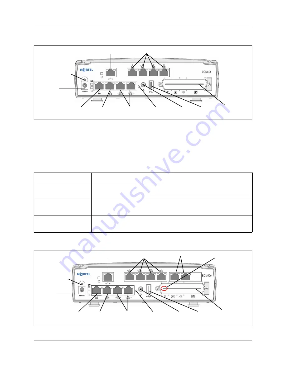
Standard main unit (BCM50e shown) ports and connectors

BRI main units

The tabl

BRI main units descriptions

 on page 14 describes the standard main units, and the figure 

BRI main unit (BCM50be shown) ports and connectors

 on page 14 shows a BRI main unit. The 

other BRI main units have similar ports and connectors. 

Figure 2   

BRI main unit (BCM50be shown) ports and connectors

Table 7   

BRI main units descriptions

BRI main units

Description

BCM50b main unit (with 
Telephony only)

The BCM50b main unit provides similar functionality to the BCM50 main unit. The 
difference is that the BCM50b main unit has two integrated BRI ports that replace the 
four analog lines on the RJ-21 telephony connector. 

BCM50ba main unit (with 
ADSL router)

The BCM50ba main unit provides similar functionality to the BCM50a main unit. The 
difference is that the BCM50ba main unit has two integrated BRI ports that replace 
the four analog lines on the RJ-21 telephony connector. 

BCM50be main unit (with 
Ethernet router)

The BCM50be main unit provides similar functionality to the BCM50e main unit. The 
difference is that the BCM50be main unit has two integrated BRI ports that replace 
the four analog lines on the RJ-21 telephony connector.

USB 

LAN
(port 1)

Expansion/LAN
(port 2, port 3)

WAN

Additional LAN

OAM
(port 0)

RJ-21 telephony 
connector

Power

Retention-clip 
mounting hole

Music 
source

Reset 
switch

USB 

LAN
(port 1)

Expansion/LAN
(port 2, port 3)

WAN

Additional LAN

OAM
(port 0)

RJ-21 telephony 
connector

Power

Retention-clip 
mounting hole

Music 
source

Reset 
switch

BRI ports

The 4 lines 
on the RJ-21 
telephony 
connector are 
not available 
with the BRI 
ports.

Summary of Contents for BCM50 3.0

Page 1: ...BCM50 3 0 Business Communications Manager Document Status Standard Document Number NN40020 308 Document Version 02 01 Part Code N0107120 Date August 2007 Installation Checklist and Quick Start Guide...

Page 2: ...presented without express or implied warranty Users must take full responsibility for their applications of any products specified in this document The information in this document is proprietary to...

Page 3: ...e CPU shall include systems with redundant processing units and Affix to each copy of licensed software made by it in the same form and location a reproduction of the copyright notices trademarks and...

Page 4: ...NORTEL NETWORKS AS IS AND WITHOUT WARRANTY OF ANY KIND OR NATURE WRITTEN OR ORAL EXPRESS OR IMPLIED INCLUDING WITHOUT LIMITATION THE IMPLIED WARRANTIES OF MERCHANTABILITY AND OF FITNESS FOR A PARTICU...

Page 5: ...ndard main units 13 BRI main units 14 Expansion units and media bay modules 15 Additional hardware 15 Nortel Business Element Manager 16 Startup Profile 16 Chapter 3 Hardware installation 17 Main unit...

Page 6: ...ntegrated router 33 BCM50a BCM50e BCM50ba or BCM50be main unit with integrated router 34 WAN connection 35 Telephone installation 36 Chapter 4 System configuration 37 Connect to the system 37 BCM Web...

Page 7: ...iguring BCM50 systems For more information about installing and configuring a BCM50 system see the Installation and Maintenance Guide Precautions Nortel recommends that you read this entire document b...

Page 8: ...ansion unit Media bay module installation on page 23 9 min Optional Install the BCM50 expansion unit Rack mount Wall mount Desk mount Expansion unit installation on page 25 3 min Apply power to the BC...

Page 9: ...n the number and type of items installed Table 2 Default IP addresses Port IP address subnet mask New IP address OAM port see Note 10 10 11 1 255 255 255 252 BCM50 or BCM50b LAN no router 192 168 1 2...

Page 10: ...feet an optional plywood backboard 3 4 in 2 cm thick for wall mount installations Phillips 2 screwdriver Common screwdriver Pliers Antistatic ground strap Connecting tool 25 pair cable with RJ 21 conn...

Page 11: ...ystem complies with the electrical requirements F Ensure that the system complies with the site telephony wiring requirements Main unit components checklist Check that you have the following component...

Page 12: ...eck that you have the following components and inspect the components for any damage F one expansion unit F one expansion unit power supply F one power supply cable F one expansion cable shielded Ethe...

Page 13: ...unit The other standard main units have similar ports and connectors Table 6 Standard main units descriptions Standard main units Description BCM50 main unit with telephony only The BCM50 main unit p...

Page 14: ...tor BCM50ba main unit with ADSL router The BCM50ba main unit provides similar functionality to the BCM50a main unit The difference is that the BCM50ba main unit has two integrated BRI ports that repla...

Page 15: ...mount bracket A bracket designed for mounting a BCM50 unit main unit or expansion unit to a wall An optional wiring field card WFC which provides RJ 45 connectors for all main unit trunk and station i...

Page 16: ...adds about 5 minutes to the time for the BCM50 system to boot To use the Startup Profile template you need a computer with a USB port Microsoft Excel 2000 or later the Nortel BCM50 Startup Profile tem...

Page 17: ...the same manner Make sure you install the expansion units close enough to the main unit so you can connect the supplied 5 m 16 ft expansion cable between the expansion unit and main unit Nortel provi...

Page 18: ...on the rack so that the feet of the unit fit in the depressions in the shelf 2 Move the unit forward until the feet touch the front side of the depressions 3 Slide the unit back until the feet click...

Page 19: ...install the patch panel 2 Position the patch panel in the rack 3 Align the holes in the patch panel with the holes in the equipment rack rails 4 Fasten the patch panel to the rack using the four rack...

Page 20: ...acket by removing the alignment tabs If this is the only unit in the BCM50 system remove the alignment tabs on the right side of the wall mount bracket If this is the last unit on a BCM50 system with...

Page 21: ...e left lock position 6 Use the supplied screw to secure the wall mount lock in position 7 Repeat steps 1 to 6 to install additional BCM50 units 8 Install the power supply using a method appropriate fo...

Page 22: ...you leave enough space around the unit for ventilation and access to the cables 4 If the BCM50 system requires additional units install the other units on top of or beside the existing BCM50 unit To...

Page 23: ...a rack on a wall or on a desktop For more detailed installation instructions for the power supply mounting enclosure see the Nortel BCM50 Power Supply Mounting Enclosure N0118043 To install a power s...

Page 24: ...to a grounded metal surface 2 With the face of the MBM toward you insert the MBM into the expansion unit Table 10 GASM8 dip switch settings switches 1 3 Switch Description Setting Switch 1 Firmware do...

Page 25: ...ith the expansion unit If you do not have the expansion cable you can use a shielded category 5e compliant Ethernet cable maximum length of 10 m 3 Plug one end of the expansion cable into the expansio...

Page 26: ...the ac power source wall outlet The BCM50 system boots Telephony connector For more information see the chapter Connecting the cables to the BCM50 system in the Installation and Maintenance Guide You...

Page 27: ...hey are not available on the BRI series b series main units which have two BRI ports instead 5 30 Tip White Slate Analog telephone 413 233 5 Ring Slate White 6 31 Tip Red Blue Analog telephone 414 234...

Page 28: ...Tip Yellow Green Digital telephone 408 228 18 Ring Green Yellow 19 44 Tip Yellow Brown Digital telephone 407 227 19 Ring Brown Yellow 20 45 Tip Yellow Slate Digital telephone 406 226 20 Ring Slate Ye...

Page 29: ...BRI port wiring Pin Signal Signal on system side 1 No connection No connection 2 No connection No connection 3 Receive Rx Tx 4 Transmit Tx Rx 5 Transmit Tx Rx 6 Receive Rx Tx 7 No connection No conne...

Page 30: ...used slots The covers on all units must be in place at the completion of any servicing Warning Electrical shock warning The MBMs were safety approved for installation into the expansion unit The insta...

Page 31: ...e hazards of working with telephony equipment and wiring They must be experienced in techniques that minimize any danger of shock or equipment damage Leakage currents Service personnel must be alert t...

Page 32: ...on the MBM 4 Connect the other end of the cable to the telephone company demarcation blocks of the building Connect extensions to the expansion unit Extensions connect to the expansion unit through t...

Page 33: ...n integrated router you can activate either the DHCP server on the main unit or the DHCP server on the integrated router through Element Manager Configuration Data Services DHCP Server General Setting...

Page 34: ...upply to the IP Phones It uses the top 20 percent of a subnet For example If the external DHCP server supplies the IP address 177 218 21 45 subnet mask is 255 255 255 0 to the BCM50 then the BCM50 DHC...

Page 35: ...ts the BCM50e and BCM50be with Ethernet router and the BCM50a and BCM50ba with ADSL router contain a router card On the BCM50e and BCM50be the WAN port is an RJ 45 port On the BCM50a and BCM50ba the W...

Page 36: ...lephones For more information about the supported telephones see the Telephony Device Installation Guide NN40020 309 For more information about installing telephones see the chapter Installing telepho...

Page 37: ...to the LAN Then you can configure the BCM50 system through Element Manager from any PC connected to the LAN If you can connect through a LAN connection proceed to BCM Web page downloads on page 38 If...

Page 38: ...Enter the username and password Defaults are Username nnadmin Password PlsChgMe 3 Click OK The Welcome to BCM Web page appears To download and install Element Manager 1 Access the BCM Web page See To...

Page 39: ...only one keycode To generate a keycode through the Nortel Keycode Retrieval System KRS you require Username and password for the KRS http www nortel com servsup krs BCM50 authorization code for each...

Page 40: ...t user ID numeric Telset password numeric Configuration Administrator Access Accounts and Privileges View by Accounts tab UserAccount Feature 9 8 User Accounts System System name Configuration System...

Page 41: ...guring the system see the online Help within Element Manager IP Phones Enable registration Enable global pwd Global pwd Auto assign DNs Advertisement logo Configuration Resources Telephony Resources I...

Page 42: ...Profile consist of the system ID followed by the appropriate extension 6 In the Startup Profile editor enter the remaining information that you want loaded onto the BCM50 system The Startup Profile ed...

Page 43: ...o configure DHCP server settings 1 From the Configuration tab click the Data Services folder to expand it 2 Select DHCP Server 3 Select the General Settings tab 4 If you have a main unit with an integ...

Page 44: ...the Resources folder to expand it 3 Select Telephony Resources from the Resources folder See the figure Telephony Resources page on page 44 Figure 9 Telephony Resources page 4 From the Modules section...

Page 45: ...llowing parameters Security policies see the Administration Guide Modem settings see the Networking Configuration Guide Software updates see the Administration Guide Voice mail for information about u...

Page 46: ...46 Chapter 4 System configuration NN40020 308...

Reviews: