


5
Figure 2
Table 1
• Provide power supply for the unit in accordance with the
unit wiring diagram, and the unit rating plate. Connect
the line-voltage leads to the terminals on the contactor
inside the control compartment.
• Use only copper wire for the line voltage power supply
listed conduit and a conduit connector for connecting
the supply wires to the unit. Use of rain tight conduit is
recommended.
• 208/230 Volt units are shipped from the factory wired
for 230 volt operation. For 208V operation, remove the
lead from the transformer terminal marked 240V and
connect it to the terminal marked 208V.
• Optional equipment requiring connection to the power
or control circuits must be wired in strict accordance of
the NEC (ANSI/NFPA 70), applicable local codes, and
the instructions provided with the equipment.
grounding
Warning:
the unit cabinet must have an uninterrupted or
unbroken electrical ground to minimize personal
injury if an electrical fault should occur. do not
use gas piping as an electrical ground!
This unit must be electrically grounded in accordance
with local codes or, in the absence of local codes, with
the National Electrical Code (ANSI/NFPA 70) or the CSA
C22.1 Electrical Code. Use the grounding lug provided
in the control box for grounding the unit.
coreSense
tm
diagnostics module
(Select models only)
The CoreSense
TM
Diagnostics Module (
) is a
breakthrough innovation for troubleshooting heat pump
and air conditioning system failures. The module installs
easily in the electrical box of the outdoor unit near the
compressor contactor.By using the compressor as
a sensor, CoreSense Diagnostics helps the service
technician more accurately troubleshoot system and
compressor fault conditions.
A flashing LED indicator communicates the ALERT code
and a diagnostic key is also imprinted on the side of the
module to quickly direct the technician to the root cause
of a problem.
Alert identification codes are also listed in
Compressor Protection
The CoreSense
TM
Diagnostics module utilizes proprietary
algorithms to protect the compressor and system from
repeated trips of system pressure controls and the
compressor internal overload. The protection terminal
of the module should be wired in series with the system
low pressure and high pressure cutouts, as well as the
compressor contactor. When the module detects a series
of trips as described below, it will activate a lockout feature
that opens the normally closed protection contacts in
the module, thereby cutting power to the contactor and
shutting off the compressor.
copper Wire SiZe — aWg
(1% Voltage drop)
Supply Wire length-Feet
Supply circuit
ampacity
200
150
100
50
6
8
10
14
15
4
6
8
12
20
4
6
8
10
25
4
4
6
10
30
3
4
6
8
35
3
4
6
8
40
2
3
4
6
45
2
3
4
6
50
2
3
4
6
55
1
2
3
4
60
Wire Size based on N.E.C. for 60° type copper conductors.
table 1. copper Wire Size
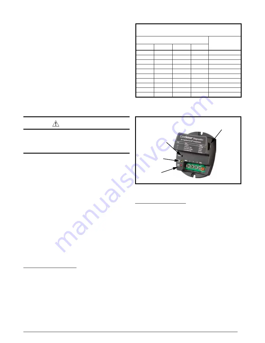
Figure 2. coreSense
tm
diagnostics module
Compressor
Common Wire
Reset Button
Trip / Lock
(Red LED)
Run / Alert
(Yellow LED)
Resetting Alert Codes
When the CoreSense
TM
Diagnostics module has detected a
series of adverse conditions that have caused it to lockout
the compressor, and after the issue has been resolved,
it is necessary to manually reset the module in order to
clear the present alert code.
The primary way of clearing the code and resetting the
alert is to press the reset button located on the module.
note:
Pressing the reset will require a pin or a mini
electronics screwdriver. This button must be pressed and
held for a minimum of one second for the module to be
reset. Pressing the reset button clears the immediate lock
code and the seven day operating history. It will not clear
the permanent module history. In the case of the three-
wire module, the codes can be reset or cleared by cycling
power to the module. This can be done by disengaging
the Common (C) terminal. This will not clear the seven
day operating history.


