


Page 14 Reznor, PVE, Installation Manual EN 2019-11, D301113 iss D
Natural ventilation openings to the
heated space
When the heater(s) are to be installed in a
heated space with an air change of less than
0.5 / hour and without the connection of
combustion ductwork. Then provision for low
level natural ventila tion will be necessary.
The minimum free area of the low level natural
ventilation opening shall be
2 cm
2
for each kW of rated heat input
The low level natural ventilation opening
should be situated on an external wall and
be within 1000 mm of floor level for natural
gas and ideally at floor level for L.P.G gas
installations but in any event no higher than
250 mm.
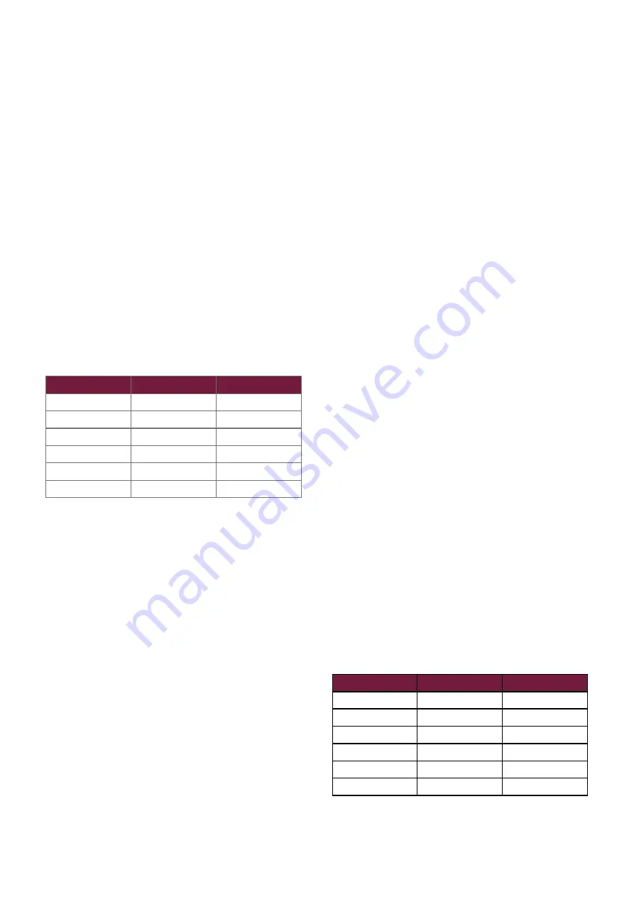
Model
High cm
2
Low cm
2
30
None
64
50
None
107
72
None
158
95
None
211
120
None
263
145
None
315
Table 8 : Minimum Free Area Of Natural
Ventilation Opening (heated space)
When the heater(s) are to be installed in a
heated space with an air change of less than
0.5 / hour and without the connection of
combustion ductwork.
Using a mechanical ventilation system, rather
than ventilation openings then
• The heated space needs to be mechanically
ventilated so that the air change is equal or
greater than 0.5/hour.
• ONLY USE input type mechanical
ventilation with a natural or mechanical
extraction system
• DO NOT use mechanical extraction with a
natural inlet
• It is necessary to provide an automatic
means to safely inhibit heater(s) operation
should mechanical air supply fail for any
reason
Heaters installed within a plant
room or enclosure.
For plant room applications the minimum
free area of ventilation opening will depend
upon whether the heater(s) is installed in room
sealed mode (ie with a positive connection to
atmosphere of both flue and combustion air).
Or with flue only (e.g. without the positive
connection to atmosphere of a combustion air
duct)
Where the heater(s) is installed in a plant room
and in room sealed mode (e.g. with a positive
connection to atmosphere of both flue and
combustion air) the minimum free area of
ventilation opening needs to be
• At high level 5 cm
2
for each kW of rated
heat input.
• At low level 5 cm
2
for each kW of rated
heat input
The high level ventilation opening should be
sited on an external wall and positioned as
high as is practical and always within the top
15% of the wall height.
The low level natural ventilation opening
should be situated on an external wall and
be within 1000 mm of floor level for natural
gas and ideally at floor level for L.P.G gas
installations but in any event no higher than
250 mm.
Model
High cm
2
Low cm
2
30
160
160
50
267
267
72
394
394
95
527
527
120
656
656
145
787
787
Table 9 : Minimum Free Area Of Natural
Ventilation Opening (room sealed heaters)


