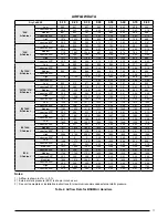
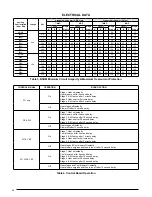
background image

17

AIRFLOW DATA

Table 2. Airflow Data for B5BM Air Handlers

Dry Coil ESP

0.10

0.20

0.30

0.40

0.50

0.60

0.70

0.80

*24K

A-Cabinet

Low

683

647

607

563

515

463

406

345

Corrected ESP

1

0.00

0.07

0.19

0.30

0.42

0.53

0.65

0.76

Medium

861

823

781

734

682

625

564

498

Corrected ESP

1

0.00

0.00

0.11

0.23

0.36

0.48

0.60

0.72

High

1072

1026

975

920

860

797

730

659

Corrected ESP

1

0.00

0.00

0.00

0.14

0.27

0.40

0.53

0.67

*30K

A-Cabinet

Low

849

825

793

753

704

647

581

508

Corrected ESP

1

0.00

0.04

0.15

0.27

0.38

0.50

0.62

0.74

Medium

1118

1087

1046

997

940

874

799

717

Corrected ESP

1

0.00

0.00

0.04

0.17

0.29

0.42

0.55

0.68

High

1277

1233

1184

1130

1070

1005

935

860

Corrected ESP

1

0.00

0.00

0.00

0.10

0.23

0.36

0.49

0.63

*24/*25K

B-Cabinet

Low

708

690

664

628

584

532

471

401

Corrected ESP

1

0.08

0.19

0.30

0.41

0.53

0.64

0.76

Medium

909

904

886

854

810

753

683

600

Corrected ESP

1

0.10

0.22

0.33

0.46

0.58

0.71

High

1118

1132

1126

1101

1056

992

908

805

Corrected ESP

1

0.09

0.22

0.35

0.49

0.64

*30/*36/*37K

B-Cabinet

Low

953

915

871

821

764

701

631

555

Corrected ESP

1

0.00

0.04

0.16

0.27

0.39

0.51

0.62

0.74

Medium

1265

1232

1188

1133

1067

991

903

805

Corrected ESP

1

0.00

0.00

0.03

0.15

0.28

0.41

0.54

0.68

High

1427

1385

1333

1270

1196

1113

1018

913

Corrected ESP

1

0.00

0.00

0.00

0.09

0.23

0.36

0.50

0.64

*42/*48K

B-Cabinet

Low

1324

1302

1271

1233

1187

1134

1072

1003

Corrected ESP

1

0.00

0.06

0.17

0.27

0.38

0.49

0.61

0.72

Medium

1485

1455

1418

1373

1320

1260

1193

1118

Corrected ESP

1

0.00

0.00

0.13

0.24

0.36

0.47

0.58

0.70

High

1637

1601

1558

1506

1447

1380

1305

1223

Corrected ESP

1

0.00

0.00

0.00

0.21

0.33

0.44

0.56

0.68

*48/*49K

C-Cabinet

Low

1605

1606

1592

1565

1524

1468

1399

1316

Corrected ESP

1

0

0.11

0.21

0.31

0.42

0.52

0.63

0.74

Medium

1977

1939

1890

1830

1758

1675

1580

1474

Corrected ESP

1

0

0

0.18

0.28

0.39

0.50

0.61

0.72

High

2264

2182

2095

2003

1906

1805

1698

1586

Corrected ESP

1

0

0

0

0.26

0.37

0.49

0.60

0.71

 *60K

C-Cabinet

Low

1348

1272

1198

1126

1056

988

922

858

Corrected ESP

1

0.00

0.11

0.22

0.33

0.44

0.55

0.65

0.76

Med-Low

1517

1455

1390

1325

1258

1189

1120

1048

Corrected ESP

1

0.00

0.00

0.19

0.30

0.41

0.52

0.63

0.74

Medium

1799

1752

1702

1650

1596

1539

1481

1420

Corrected ESP

1

0.00

0.00

0.00

0.25

0.36

0.47

0.58

0.69

Med-High

1956

1910

1862

1811

1756

1699

1639

1575

Corrected ESP

1

0.00

0.00

0.00

0.22

0.33

0.44

0.55

0.66

High

2146

2099

2050

2000

1948

1894

1839

1783

Corrected ESP

1

0.00

0.00

0.00

0.00

0.29

0.40

0.51

0.62

Notes:

1)  Airflow is shown in cfm, +/- 5%.
2)  External static pressure (ESP) is shown in inches w.c.
3)  See unit nameplate or installation instructions for maximum recommended external static pressure.

Summary of Contents for B5BM

Page 1: ...ion service adjustment or maintenance may cause explosion fire electrical shock or other hazardous conditions which may result in personal injury or property damage Unless otherwise noted in these ins...

Page 2: ...ns 11 Control Board 12 Twinning 12 Heater Kits 12 Startup Adjustments 12 Before You Start the Unit 12 Refrigerant Charging 13 Air Circulation 13 Running the Blower Continuously 13 Continuous Low Speed...

Page 3: ...his unit Unqualified individuals should not attempt to interpret these instructions or install this equipment Failure to follow safety recommendations could result in possible damage to the equipment...

Page 4: ...ervice access and noise The dimensions of the room or alcove must be able to accommodate the overall size of the unit and the installation clearances listed in Figure 1 Physical dimensions for this ai...

Page 5: ...duct opening or filter rack located in the bottom of the unit Accessing the filter does not require tools and can be removed from the front of the unit by removing the filter door See Unit Maintenanc...

Page 6: ...hen installing the unit in an upflow configuration All return air must enter from the bottom of the unit A typical upflow unit is shown in Figure 2 Downflow Installations Thedownflowaccessorykit SeeTe...

Page 7: ...orizontal drain pan into the open and unused drain hole in the drain pan at the bottom of the unit to block bypass air 4 Remove the corresponding drain line knockout from the coil access door to allow...

Page 8: ...quid lines must be sized in accordance with the condensing unit specifications See Figure 11 page 16 for liquid and suction line locations When connecting refrigerant linesets together it is recommend...

Page 9: ...h lineset tubes to proper length in accordance with the outdoor unit specifications Verify the ends are round clean and free of any burrs 4 Positiongrommetonlinesetwithsufficientdistanceaway from braz...

Page 10: ...ccurring 7 Wrap the refrigerant lines with pressure sensitive neoprene or other suitable material especially where the lines enter the opening in the sheet metal 8 Evacuatethesystemofmoistureandnon co...

Page 11: ...the unit Use only copper wire for the line voltage power supply to this unit Use proper code agency listed conduit and a conduit connector for connecting the supply wires to the unit Aluminum supply...

Page 12: ...vided 3 Connect the heater kit plug with the mating receptacle on the air handler control board If a heater kit is not installed 1 Remove the 2 wire plug of the air handler by cutting the wires and di...

Page 13: ...un for several minutes and then set the thermostat s temperature below room temperature Verify the blower cycles off with the thermostat Minimum Electric Heat Airflow The minimum electric heat airflow...

Page 14: ...he factory It is recommended that the filter be cleaned or replaced monthly Newly built or recently renovated homes may requiremorefrequentchanginguntiltheconstructiondust has minimized Filter sizes s...

Page 15: ...11 4 15 8 17 8 11 4 3 1 4 2 5 8 11 8 K O typ 13 4 K O typ 1 7 8 3 5 8 5 5 8 DETAIL D 3 1 4 2 1 4 15 1 4 13 SUCTION LIQUID W 1 1 8 1 7 8 7 8 K O H 22 A Cabinet Size H W A Detail D A 43 5 16 14 3 16 12...

Page 16: ...Motor Mount Kit Blower Motor Transformer Capacitor Circuit Breaker 60A Heating Element Assembly Filter Tracks Blower Wheel Blower Housing Motor Control Board Control Board Filter Door Upper Door Assem...

Page 17: ...1270 1196 1113 1018 913 Corrected ESP1 0 00 0 00 0 00 0 09 0 23 0 36 0 50 0 64 42 48K B Cabinet Low 1324 1302 1271 1233 1187 1134 1072 1003 Corrected ESP1 0 00 0 06 0 17 0 27 0 38 0 49 0 61 0 72 Medi...

Page 18: ...Conditioner with Variable Speed Air Handler Typical 2 Stage Cooling Heat Pump with Optional Outdoor Thermostat Variable Speed Air Handler W2 W1 O Y Y2 G R C W2 W1 O Y Y2 G R C Y2 Y2 Y2 Y2 W1 W3 R Y1...

Page 19: ...19 C R G Y Y2 O W1 W2 Y1 24VAC COM FUSE P2 P3 X13 COM X13 HEAT X13 COOL XFMR L1 VSPOWER L1 L2COM L2 L2 Figure 13 Motor Control Board...

Page 20: ...8 9 10 11 12 13 14 15 16 G C O HUM Y1 W R HUM Y Y2 L2 COM 2 L2 L2COM L1 VS POWER XFMR COOL HEAT Y1 HEATER PLUG P3 1 2 3 4 5 6 7 8 YELLOW BLUE RED JUMPER SELECTOR SWITCHES NOTE 1 ON 0 OFF 710544D Repl...

Page 21: ...IELD WIRING LEGEND LOW VOLTAGE HIGH VOLTAGE The blower motor speed tap connection may not be as shown See the Installation Instructions Disconnect all power before servicing Transformer may have a dua...

Page 22: ...ct all power before servicing 3 Transformer may have a dual voltage primary tap Match the tap position with the supply voltage used 4 If the Internal wiring is replaced use only 105 C copper wire of t...

Page 23: ...K GREY BLACK GREY BLUE ORANGE POWER PLUG LIMIT RED RED RED RED BLACK BLACK RED BLACK RELAY RELAY TERMINAL BLOCK for select models only CIRCUIT BREAKER Circuit breaker models only BLUE W2 W1 O Y Y2 G R...

Page 24: ...pply voltage used 4 If the Internal wiring is replaced use only 105 C copper wire of the same gauge W2 W1 O Y Y2 G R C 4 SPD MOTOR 1 2 3 5 6 4 TRANSFORMER 24V BLACK RED WHITE BLACK WHITE FUSE L2 COM 2...

Page 25: ...1 2 3 5 4 TRANSFORMER 24V BLACK RED WHITE BLACK WHITE FUSE BLOWER MOTOR PLUG C L G N N NEUTRAL G GROUND L LINE C COMMON L2 L2 L2 COM L1 L1 XFMR X13 COOL X13 HEAT 24 VAC RED COM GREY Y1 C L G N WHITE X...

Page 26: ...1 only On Stage 1 Heat on instantly Heat blower on after 3 second delay Stage 3 5 Heat on after 1 minute delay Stage 2 Heat on after 2 minute delay Stage 4 6 Heat on after 3 minute delay Off Heat stag...

Page 27: ...27...

Page 28: ...sareprimarilyintendedtoassistqualifiedindividuals experienced in the proper installation of this appliance Some local codes require licensed installation service personnel for this type of equipment P...

Reviews: