


14
UNIT MAINTENANCE
WARNING:
ELECTRICAL SHOCK, FIRE OR EXPLOSION
HAZARD
Failure to follow safety warnings exactly could
result in serious injury or property damage.
Improper servicing could result in dangerous
operation, serious injury, death or property
damage.
• Before servicing, disconnect all electrical power
to air handler.
• When servicing controls, label all wires prior
to disconnecting. Reconnect wires correctly.
• Verify proper operation after servicing.
Proper maintenance is most important to achieve the best
performance from a air handler. Some of the components
and their locations are shown in Figure 11 (page 16). If
any component of the air handler must be replaced, use
only factory authorized replacement parts specified in the
Replacement Parts List provided online.
• These maintenance instructions are primarily intended
to assist qualified technicians experienced in the proper
maintenance and operation of this appliance.
• Always reinstall the doors on the air handler after
servicing or cleaning/changing the filters. Do not operate
the air handler without all doors and covers in place.
• Verify that the thermostat is properly installed and is
not being affected by drafts or heat from lamps or other
appliances.
• To achieve the best performance and minimize
equipment failure, it is recommended that a yearly
maintenance checkup be performed. At a minimum,
this check should include the following items:
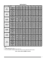
Air Filter(s) - B5 Series Air Handlers are not supplied
with a single air filter when shipped from the factory. It
is recommended that the filter be cleaned or replaced
monthly. Newly built or recently renovated homes may
require more frequent changing until the construction dust
has minimized. Filter sizes shown in Table 1 are available
at most local retailers.
WARNING:
Never operate the air handler without a filter in
place. Dust and lint in the return air can build
up on internal components, resulting in loss of
efficiency, equipment damage, and possible fire.
Filters designed to remove smaller particles such as
pollen, may require additional maintenance.
Blower Compartment - Dirt and lint can create excessive
loads on the motor resulting in higher than normal operating
temperatures and shortened service life. It is recommended
that the blower compartment be cleaned of dirt or lint
that may have accumulated in the compartment or on
the blower and motor as part of the annual inspection.
Blower Fan Wheel - Inspect the blower wheel blades
for accumulations of dirt and clean if necessary. Inspect
mounting nut for tightness when done.
Blower Motor & Assembly - Inspect the blower assembly
and motor mounting brackets for tightness and corrosion.
Correct deficiencies if necessary. The blower motor
contains sealed bearings and under normal operating
conditions, no maintenance is necessary for the life of
the equipment.
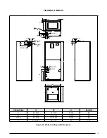
CABINET SIZE
FILTER SIZE
A
12 x 20 x 1
B
18 x 20 x 1
C
20 x 20 x 1
Table 1. Filter Sizes
TROUBLESHOOTING
If the air handler fails to operate, check the following:
• Is the electric turned on?
• Is the thermostat operating properly?
• Are the blower compartment door(s) in place?
• Is the air handler disconnect closed?
• Has the circuit breaker tripped or the control board fuse
burned open?
• Is the filter dirty or plugged?
Summary of Contents for B5BM
Page 27: ...27...


