12
on an outside wall or any other location where its
operation may be adversely affected by radiant heat from
fireplaces, sunlight, or lighting fixtures, and convective
heat from warm air registers or electrical appliances.
Refer to the thermostat manufacturer’s instruction sheet
for detailed mounting and installation information.
• Install the grommet, which is packed with the unit, in
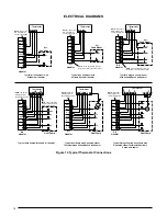
the hole for low-voltage wires. Connect the low-voltage
wiring to the thermostat and the outdoor unit and the
appropriate screw terminal located on the control board.
NOTE: When the low voltage wires are positioned in
this grommet, the grommet will prevent chafing and/or
shorting of the low voltage leads.
Control Board
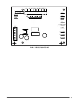
The control board in the air handler controls the timing
sequence of the elements. The board is equipped with a 3
second blower on delay and a 15 second blower off delay
in heating and a 40 second blower off delay in cooling.
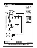
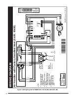
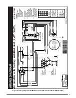
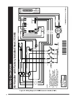
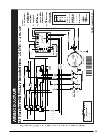
See Figure 13 (page 19).
Twinning
B5BM air handlers are not supplied with a built in twinning
capability. To connect two air handlers to a common
single stage AC condensing unit or heat pump, a twinning
kit is available for field installation. Please follow the
instructions supplied with the kit.
NOTE: Variable speed air handlers cannot be twinned.
Heater Kits
When electric heat packages with circuit breakers are
field-installed, the circuit breaker may be used as a
disconnecting means in most applications. Reference
the NEC and local codes for disconnect requirements.
If a heater kit is installed:
The B5BM air handler is shipped from the factory without
an electric heater kit installed. If Electric heat is desired,
the H6HK heater kit may be purchased separately and
field installed. Determine the correct size heater kit for your
unit by referring to the list below or the units rating label.
A Cabinet ....................................................... 15Kw max
B Cabinet ....................................................... 20Kw max
C Cabinet ....................................................... 30Kw max
1. Connect the 2 wire plug of the air handler to the mating
2 wire plug of the heater kit.
2. Connect the line voltage leads to the circuit breaker or
terminal block provided.
3. Connect the heater kit plug with the mating receptacle
on the air handler control board.
If a heater kit is not installed:
1. Remove the 2 wire plug of the air handler by cutting
the wires and discarding the plug.
2. Strip the ends of the 2 air handler wires and connect
to the line-voltage leads with the 2 wire nuts provided.
STARTUP & ADjUSTMENTS
WARNING:
The evaporator coil is shipped from the factory
with a nitrogen charge. Use caution when
preparing coils for field connections. If repairs
make it necessary for evacuation and charging,
it should only be attempted by qualified,
trained personnel thoroughly familiar with this
equipment. Some local codes require licensed
installation service personnel to service this
type of equipment. Under no circumstances
should the equipment owner attempt to install
and/or service this equipment. Failure to comply
with this warning could result in equipment
damage, personal injury, or death.
NITROGEN
HEALTH
FLAMMABILITY
REACTIVITY
0 Minimal Hazard
1 Slight Hazard
1
0
0
Before You Start the Unit
Prior to start-up, complete the following inspections:
√
Verify the unit is level and properly located with adequate
clearances for servicing the unit. See Figure 1 (pg 4).
√
Check condensate drain line(s) for proper drainage.
√
Verify the surrounding area and top of the unit is free
from obstructions and debris.
√
Check all duct connections. Make sure the duct work
is adequately sealed to prevent air leakage.
√
Check all coil connections for leaks.
√
Verify that the line voltage power leads are securely
connected and the unit is properly grounded. Make sure
all doors are installed before restoring power to the unit
√
Verify the thermostat is wired correctly. Make sure all
low voltage wires are securely connected to the correct
leads of the low voltage terminal strip.
√
Verify the power supply branch circuit overcurrent
protection is sized properly.
√
Verify filter is properly and securely installed.
IMPORTANT: Before starting the unit, install the initial
charge on units that are factory shipped with a nitrogen
holding charge:
1. Read all installation instructions first.
2. Purge the nitrogen holding charge.
3. Evacuate the unit to 350 - 500 microns.
4. Allow the unit to remain under vacuum for at least 30
minutes.
Summary of Contents for B5BM
Page 27: ...27...


