33
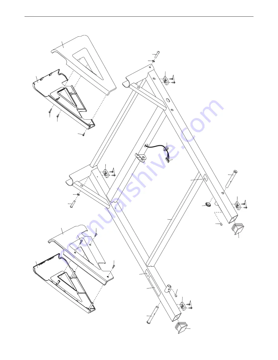
EXPLODED DRAWING C
2
10
1
36
94
80
92
24
57
84
90
3
78
81
82
83
8
17
Model No. NTL15010.1 R0612A
Page 1: ...Care IMPORTANT Please register this product see the limited warranty on the back cover of this manual before contacting Customer Care CALL TOLL FREE 1 800 TO BE FIT 1 800 862 3348 Mon Fri 6 a m 6 p m...
Page 2: ...31 ORDERING REPLACEMENT PARTS Back Cover LIMITED WARRANTY Back Cover WARNING DECAL PLACEMENT NORDICTRACK is a registered trademark of ICON IP Inc This drawing shows the locations of the warning decal...
Page 3: ...priate outlet see page 13 To avoid overloading the circuit do not plug other electrical devices except for low power devices such as cell phone chargers into the surge suppressor or into an outlet on...
Page 4: ...20 kg to raise lower or move the incline trainer 22 Never insert any object into any opening on the incline trainer 23 Inspect and properly tighten all parts of the incline trainer regularly 24 DANGER...
Page 5: ...front cover of this manual To help us assist you note the product model number and serial number before contacting us The model number and the location of the serial number decal are shown on the fro...
Page 6: ...following the key number is the quantity used for assembly Note If a part is not in the hardware kit check to see if it is preat tached Extra hardware may be included 8 x 3 4 Screw 1 8 8 x 1 Tek Scre...
Page 7: ...e it off with a soft cloth and a mild non abrasive cleaner To identify small parts see page 6 Assembly requires the following tools the included hex keys one Phillips screwdriver To avoid damaging par...
Page 8: ...n them Be careful not to pinch the Upright Wire not shown in the Upright Attach the other Upright not shown as described above Note There is not a wire on the left side 2 77 17 80 8 5 8 3 89 37 A A 3...
Page 9: ...sary to slide the Console Crossbar 101 to align the holes Then tighten the two 8 x 1 Screws 102 Repeat this step on the other side of the incline trainer 4 Have a second person hold the console assem...
Page 10: ...the two R pulse wires L R R 7 5 L Pulse Wire Start First 93 77 8 R Pulse Wires Console Assembly 6 Tighten two 8 x 3 4 Screws 1 into the Console Base 87 Do not overtighten the Screws Identify the Right...
Page 11: ...left Upright 77 Insert the pulse wire from the left handrail assembly into the hole in the top of the Upright and pull it out of the end of the Upright Set the Left Handrail Assembly 86 onto the left...
Page 12: ...e 1 Step Incline button numbered 40 on the console The Frame 58 will adjust to an incline of 40 percent Then turn off the incline trainer and unplug the power cord Identify the Left Inside Cover 3 and...
Page 13: ...power cord into a surge suppressor and plug the surge suppressor into an appropriate outlet that is properly installed and grounded in accordance with all local codes and ordinances The outlet must b...
Page 14: ...use the manual mode you can change the speed and incline of the incline trainer with the touch of a button As you exercise the console will display instant exer cise feedback You can also measure your...
Page 15: ...ically rise to the maximum incline level and then return to the minimum incline level This will calibrate the incline of the incline trainer If the incline does not automatically change see step 4 at...
Page 16: ...ainer will gradually adjust to the selected incline setting Note For your safety as you adjust the incline set ting to negative levels or to levels above 15 the maximum speed of the incline trainer wi...
Page 17: ...l appear next one or two dashes will appear and then your heart rate will be shown For the most accurate heart rate read ing continue to hold the contacts for about 15 seconds 7 Turn on the fan if des...
Page 18: ...ncline setting is programmed for the next segment the incline trainer will automatically adjust to the new speed and or incline setting The workout will continue in this way until the last segment of...
Page 19: ...e display will show the duration of the workout the distance you will walk or run and the approximate number of calories you will burn The display may also show the name of the workout 5 Start the wor...
Page 20: ...in the matrix To change the unit of mea surement press the Enter button To view distance in miles select ENGLISH To view distance in kilometers select METRIC Default Menu The default menu will appear...
Page 21: ...ntering the password press the Done button A numerical code and a web address will appear in the matrix Go to the web address on your internet compatible device Log in to your iFit Live account on the...
Page 22: ...check the IP address and the previous instructions of this step Follow the instructions on the web page to connect the incline trainer to your wireless network Note A warning may appear stating that t...
Page 23: ...rolls freely on the wheels CAUTION To decrease the possibil ity of injury or of damage to the incline trainer do not lift the incline trainer by the plastic belly pan Do not pull on the console Caref...
Page 24: ...off during use a Check the power switch see the drawing above If the switch has tripped wait for five minutes and then press the switch back in b Make sure that the power cord is plugged in If the pow...
Page 25: ...le SYMPTOM The walking belt slows when walked on a Use only a surge suppressor that meets all of the specifications described on page 13 b If the walking belt is overtightened incline trainer performa...
Page 26: ...to 40 percent Remove the key and UNPLUG THE POWER CORD Using the hex key turn both idler roller screws clockwise 1 4 of a turn When the walking belt is correctly tightened you should be able to lift e...
Page 27: ...c Exercise If your goal is to strengthen your cardiovascular system you must perform aerobic exercise which is activity that requires large amounts of oxygen for prolonged periods of time For aerobic...
Page 28: ...lles Stretch With one leg in front of the other reach forward and place your hands against a wall Keep your back leg straight and your back foot flat on the floor Bend your front leg lean forward and...
Page 29: ...2 Belt Guide 44 1 Walking Platform 45 1 Rear Cover 46 4 Incline Motor Bushing 47 1 Idler Roller 48 1 Walking Belt 49 1 Front Hood 50 1 Power Cord 51 1 Grommet 52 1 Belly Pan Cover 53 1 Power Switch 54...
Page 30: ...2 4 8 x 1 Screw 103 1 Crossbar 104 2 Console Clamp 105 2 3 8 x 2 1 2 Screw 106 1 1 4 Nut User s Manual Note Specifications are subject to change without notice For information about ordering replaceme...
Page 31: ...38 35 35 1 1 1 1 1 52 35 35 35 39 21 21 23 23 23 25 25 42 41 48 44 43 47 43 40 23 1 1 1 68 62 72 66 35 35 35 35 35 35 35 35 1 1 1 1 45 36 36 18 18 85 85 1 1 1 1 1 1 1 28 28 28 28 28 28 28 28 1 1 1 1 1...
Page 32: ...33 33 108 58 75 29 33 22 31 69 13 13 13 70 13 30 30 13 30 26 26 32 46 33 1 32 63 65 64 1 1 1 46 46 60 56 20 22 31 55 46 74 73 79 74 73 79 73 49 61 91 108 108 13 59 13 13 1 91 13 71 1 7 7 7 7 73 106 M...
Page 33: ...33 EXPLODED DRAWING C 2 10 2 10 2 10 2 10 1 1 36 1 1 94 80 92 24 57 84 57 84 24 90 3 78 81 82 83 82 81 8 17 8 17 36 Model No NTL15010 1 R0612A...
Page 34: ...34 EXPLODED DRAWING D 77 78 4 9 77 8 5 8 5 103 76 1 102 102 104 104 1 1 1 101 11 11 98 98 8 5 8 5 4 9 8 8 1 1 1 1 97 13 32 12 6 32 12 6 105 105 86 93 Model No NTL15010 1 R0612A...
Page 35: ...35 EXPLODED DRAWING E 1 1 1 1 16 1 1 1 19 87 1 1 67 96 96 100 99 99 37 88 89 16 16 16 16 16 16 16 34 34 100 100 100 1 1 1 1 Model No NTL15010 1 R0612A...
Page 36: ...damage to the product This warranty will automatically be voided if the product is used as a store display model if the product is purchased or transported outside the USA if all instructions in this...