


1-Nov-2021
Page 20
001200MAN-09
Ductwork
Zoning
Zoning can be done with heat pumps that have 2-stage
compressors, but only to a limited extent. It is recommended
that no zone be less than 1/3 the total area, to avoid problems of
high airflow and noise through one zone or safety control trips
due to capacity mismatch between heat pump and zones.
The airflow can be reduced by 15% by making a dry con-
tact across
AR1
and
AR2
on the thermostat terminal strip in the
heat pump’s electrical box, as show in
Wiring
chapter.
When only one zone of 50% or less is calling for heating or
cooling, the compressor should be limited to
stage 1
operation
by the zone controller by sending only a
Y1
(without Y2) control
signal. Stage 1 corresponds to ~67% compressor capacity and
~80% airflow.
Refer to airflow tables in the
Model Specific Information
chapter for airflows with the various reductions.
Duct Systems - General
Ductwork layout for a heat pump will differ from traditional
hot air furnace design in the number of leads and size of main
trunks required. Air temperature leaving the heat pump is
normally
95º -105ºF (35-40ºC)
, much cooler than that of a
conventional fossil fuel furnace. To compensate for this, larger
volumes of lower temperature air must be moved and
consequently duct sizing must be able to accommodate the
greater airflow without creating a high static pressure or high
velocity at the floor diffusers.
A duct system capable of supplying the required airflow is
of utmost importance. Maritime Geothermal Ltd. recommends
that the external static pressure from the duct system be kept
below 0.2 inches of water total. In some instances the number
of floor diffusers will actually double when compared to the
number that would be used for a hot air oil-fired furnace. Refer
to following tables.
1. Generally allow
100 cfm
for each floor grill.
2. All leads to the grills should be 6'' in diameter (28sq.in. each).
3. The main hot air trunks should be at least 75% of the square
surface area of leads being fed at any given point.
4. Return air grills should have a minimum of the same total
square surface area as the total of the supply grills.
5. The square surface area of the return trunks should equal
the square surface area of the grills being handled at any
given point along the trunk.
It is
VERY IMPORTANT
that all turns in both the supply
trunks and the return trunks be made with
TURNING RADII
. Air
act like a fluid and, just like water, pressure drop is increased
when air is forced to change direction rapidly around a sharp or
irregular corner.
It is recommended that flexible collars be used to connect
the main trunks to the heat pump. This helps prevent any vibra-
tions from travelling down the ductwork. If a plenum heater is
installed, the collar should be at least 12” away from the heater
elements.
If desired, the first 5-10 feet of the main supply trunks can
be insulated internally with acoustical duct insulation to further
inhibit any noise from the unit from travelling down the ductwork.
If a plenum heater is installed, insulation should not be placed
within 12” of the heater elements.
Duct Systems - Grill Layout
Most forced air heating systems in homes have the floor
grills placed around the perimeter of the room. Supply grills
should be placed under a window when possible to help prevent
condensation on the window. As mentioned in the previous sub
-section, supply grill leads should be 6'' in diameter (28 square
inches each) to allow
100 cfm
of airflow.
In a typical new construction, there should be one supply
grill for every 100 square feet of area in the room. When rooms
require more than one grill, they should be placed in a manner
that promotes even heat distribution, such as one at each end of
the room. It is always a good idea to place a damper in each
grill supply or place adjustable grills so that any imbalances in
the heat distribution can be corrected.
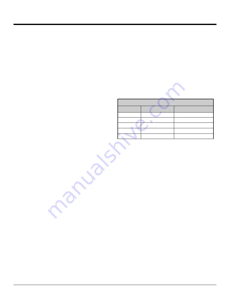
The total number of supply grills available is based on the
heat pump nominal airflow. The table
shows the number of
grills recommended per heat pump size.
Return grills should be mounted on the floor. At minimum
they should be the same size as the supply grill,
it is highly rec-
ommended that they be 25% to 50% larger than the total
supply.
They should be placed opposite the supply grills
when possible to ensure distribution across the room. For
rooms requiring more than one supply grill, it may be possible to
use one larger return grill if it can be centrally positioned oppo-
site of the supply grills, however it is preferred to have one re-
turn for each supply to optimize heat distribution across the
room.
Thermostat Location
Most homes are a single ducted air zone with one thermo-
stat. The thermostat should be centrally located within the
home, typically on the main floor. It should be placed away from
any supply grills, and should not be positioned directly above a
return grill. Most installations have the thermostat located in a
hallway, or on the inner wall of the living room. It should be not-
ed that most homes do not have any supply ducts in the hall-
way. This can lead to a temperature lag at the thermostat if
there is very little air movement in the hallway, causing the
home to be warmer than indicated by the thermostat.
Plenum Heater
The plenum heater will be usually installed inside the heat
pump, as described in the
Installation Basics
section. If the
blower is installed in the side discharge position, the plenum
heater will be installed in the discharge ductwork outside the
unit, at least 12” away from any flexible duct collars. There is an
accessory plenum heater with a wider cage profile available that
is more suitable for duct installation.
TABLE 10 - Heat Pump Size vs. Hot Air Grills
Model
Size (tons)
# of Grills (@100 cfm)
45
3
12
55
4
15
65
5
19
75
6
21
80
6.5
23
Summary of Contents for R-45
Page 11: ...1 Nov 2021 Page 11 001200MAN 09...
Page 15: ...1 Nov 2021 Page 15 001200MAN 09...
Page 16: ...1 Nov 2021 Page 16 001200MAN 09...
Page 18: ...1 Nov 2021 Page 18 001200MAN 09...
Page 19: ...1 Nov 2021 Page 19 001200MAN 09...
Page 21: ...1 Nov 2021 Page 21 001200MAN 09...
Page 25: ...1 Nov 2021 Page 25 001200MAN 09...
Page 26: ...1 Nov 2021 Page 26 001200MAN 09...
Page 27: ...1 Nov 2021 Page 27 001200MAN 09...
Page 28: ...1 Nov 2021 Page 28 001200MAN 09...
Page 29: ...1 Nov 2021 Page 29 001200MAN 09...
Page 33: ...1 Nov 2021 Page 33 001200MAN 09...
Page 34: ...1 Nov 2021 Page 34 001200MAN 09...
Page 35: ...1 Nov 2021 Page 35 001200MAN 09...
Page 63: ...1 Nov 2021 Page 63 001200MAN 09 Wiring Diagram 208 230 1 60...
Page 64: ...1 Nov 2021 Page 64 001200MAN 09 Electrical Box Layout R 45 75 208 230 1 60...
Page 65: ...1 Nov 2021 Page 65 001200MAN 09 Electrical Box Layout R 80 208 230 1 60...
Page 66: ...1 Nov 2021 Page 66 001200MAN 09 Electrical Box Layout RH 45 75 208 230 1 60...
Page 67: ...1 Nov 2021 Page 67 001200MAN 09 Wiring Diagram 208 3 60...
Page 68: ...1 Nov 2021 Page 68 001200MAN 09 Electrical Box Layout R 45 75 208 3 60...
Page 69: ...1 Nov 2021 Page 69 001200MAN 09 Electrical Box Layout R 80 208 3 60...
Page 70: ...1 Nov 2021 Page 70 001200MAN 09 Electrical Box Layout RH 45 75 208 3 60...
Page 71: ...1 Nov 2021 Page 71 001200MAN 09 Wiring Diagram 265 277 1 60...
Page 72: ...1 Nov 2021 Page 72 001200MAN 09 Electrical Box Layout R 45 75 265 277 1 60...
Page 73: ...1 Nov 2021 Page 73 001200MAN 09 Electrical Box Layout R 80 265 277 1 60...
Page 74: ...1 Nov 2021 Page 74 001200MAN 09 Electrical Box Layout RH 45 75 265 277 1 60...
Page 75: ...1 Nov 2021 Page 75 001200MAN 09 Wiring Diagram 460 3 60...
Page 76: ...1 Nov 2021 Page 76 001200MAN 09 Electrical Box Layout R 25 75 460 3 60...
Page 77: ...1 Nov 2021 Page 77 001200MAN 09 Electrical Box Layout R 80 460 3 60...
Page 78: ...1 Nov 2021 Page 78 001200MAN 09 Electrical Box Layout RH 25 75 460 3 60...
Page 79: ...1 Nov 2021 Page 79 001200MAN 09...
Page 80: ...1 Nov 2021 Page 80 001200MAN 09...
Page 81: ...1 Nov 2021 Page 81 001200MAN 09 Dimensions R 45 Left Return...
Page 82: ...1 Nov 2021 Page 82 001200MAN 09 Dimensions R 45 Right Return...
Page 83: ...1 Nov 2021 Page 83 001200MAN 09 Dimensions R 55 65 75 Left Return...
Page 84: ...1 Nov 2021 Page 84 001200MAN 09 Dimensions R 55 65 75 Right Return...
Page 85: ...1 Nov 2021 Page 85 001200MAN 09 Dimensions R 80 Left Return...
Page 86: ...1 Nov 2021 Page 86 001200MAN 09 Dimensions R 80 Right Return...
Page 87: ...1 Nov 2021 Page 87 001200MAN 09 Dimensions RH 45 Left Return...
Page 88: ...1 Nov 2021 Page 88 001200MAN 09 Dimensions RH 45 Right Return...
Page 89: ...1 Nov 2021 Page 89 001200MAN 09 Dimensions RH 55 65 75 Left Return...
Page 90: ...1 Nov 2021 Page 90 001200MAN 09 Dimensions RH 55 65 75 Right Return...