background image

I

UK

D

E

F

NL

P

S

DK

FIN

B

GR

CZ

EE

LV

LT

H

M

PL

SK

SLO

6

Operator's guide

7. CONNECTION TO THE MAINS

1

. Ensure that mains voltage and frequency are the same as those stated on the rating plate (A) attached

to the appliance. . Ensure that the supply socket:

2

a)

b)

is properly earthed;

fulfils the requirements of the

rated current as set out on the rating plate;

complies with the IEC regulations:- thermal-magnetic

c)

switch with In = rated value as stated on the rating plate; - differential with Id sensitivity = 30 mA.

.

3

Ensure that there is no danger of explosion (AD) in the room. . Make sure the environment is suitable for

4

the power supply cable provided. The cable of the appliance is H05 VVF, designed for internal use.

5

N.B.:

. Insert the plug in the socket (do not use three-way adapters and reduction adapters).
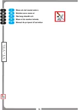
if the

equipment has been transported or stored overturned, let is rest in its correct position for at least 3 hours
before hooking it up to the mains (see fig. 5).

8. CONTROLS

The appliance features controls situated in a protected panel on the front side.

to

1. Cover lifting switch:

open and close the cover - Position II to lift - Position O to stop - Position I to lower.

to

2. Light switch:

switch on the internal lights.

to switch on the refrigeration unit.

3. Refrigeration switch:

4. Thermometer

Thermostat:

: to read the temperature in the counter.

to adjust the temperature setting.

a) Press key

to display the temperature set-point, which can be changed by pressing key

5

SET or P

6

UP

7

DOWN

or

(see fig. 6).

9. CHECKING CORRECT OPERATION

Make sure that: 1.

2.

the plug is connected;

the refrigeration unit switch is on (green light lit up);

3

4

. thermometer shows the desired temperature for the goods to be stored; . appliance is not exposed to

direct sunlight or to powerful lamps;

ambient temperature does not 30°C with 55% R.H.

5.

(climatic class 4); . there are no direct air draughts in the appliance, coming from the appliance itself,

6

owing to the presence of doors, windows, fans or conditioner outlets.

10. INTERNAL CLEANING

1.

2.

Switch off the appliance.

Check the evaporator fins for frost or ice. Should the layer of frost be too

thick, and ice drips are noted that could impair passage of air, complete defrosting should be undertaken.
Remove goods and store them in another suitable refrigerator running at the same temperature.

3.

4

Remove the plug in the bottom section of the machine. . Clean the walls and accessories with a

sponge dipped in water and sodium bicarbonate. Take care not to touch the evaporator fins, which
feature sharp edges. . Dry all parts with care and refit all components. Refit the plug before turning on

5

the appliance.

11. REPLACEMENT OF THE LAMP (VT-VTL)

1

2

3.

. Open the cover. . Switch off the appliance.

Remove the screws securing one of the lamp sockets in

place. . Remove the lamp socket, whilst holding the fluorescent tube and its protective cover. . Pull the

4

5

protective cover out of the other lamp socket. . Replace the fluorescent tube. . Refit all components by

6

7

following the above instructions in reverse order (see fig. 7).

Summary of Contents for 4554642092

Page 1: ...Bedienungsanweisung Salatbar ISOLA 4 M UM Art 4554642092 2019 07...

Page 2: ...Italiano English Deutsch Espa ol Fran ais MANUTENZIONE MAINTENANCE INSTANDHALTUNG MANTENIMIENTO ENTRETIEN I UK D E F NL P S DK FIN B GR CZ EE LV LT H M PL SK SLO 2...

Page 3: ...ANAMENTE MEDIANTE IL RUBINETTO 1 APERTURA DELL IMBALLAGGIO IMBALLAGGIO IN SCATOLA DI CARTONE 1a Tagliare la reggia sfilare la scatola verso l alto IMBALLO IN CASSA DI LEGNO 1b Schiodare le tavole di l...

Page 4: ...Tasto 6 UP Tasto 7 DOWN 9 CONTROLLO DI UN REGOLARE FUNZIONAMENTO CONTROLLARE CHE 1 2 La spina sia inserita L interruttore dell impianto refrigerante sia inserito luce verde accesa Il termometro indich...

Page 5: ...t the compressor will continue to operate leading to a wasteful consumption of electricity and poor performance Our products are for internal use only do not install outside restaurants shops Remove e...

Page 6: ...t point which can be changed by pressing key 5 SET or P 6 UP 7 DOWN or see fig 6 9 CHECKING CORRECT OPERATION Make sure that 1 2 the plug is connected the refrigeration unit switch is on green light l...

Page 7: ...ellten Produkte nicht ber die Ablagen oder Gitter hinnausstrecken d rfen Sollte es durch die 12 Luftfeuchtigkeit oder die zu k hlenden Produkte zu au ergew hnlicher Bildung von Eis auf dem Verdampfer...

Page 8: ...uf der Vorderseite befinden Zum ffnen und Schlie en der Kuppel 1 Schalter zum Anheben der Kuppel Position II Anhub Position O Stillstand Position I Absenkung Zum Einschalten der 2 Lichtschalter Innenb...

Page 9: ...a humedad del aire o de los productos que se quieren refrigerar les aconsejamos que paren el compresor y que saquen y coloquen los alimentos en espec ficos contenedores refrigerados a la misma tempera...

Page 10: ...I 2 Interruptor luz 3 Interruptor refrigeraci n 4 Term metro Sirve para encender la instalaci n refrigeradora Indica la temperatura del equipo Regula la temperatura del equipo a Si se pulsa la Termost...

Page 11: ...roduits r frig rer nous vous conseillons de fermer le compresseur et de disposer la marchandise dans un r cipient r frig r la m me temp rature pour toute la dur e n cessaire au d givrage si vous laiss...

Page 12: ...ion II pour lever Position O pour arr ter Position I pour abaisser il sert allumer la lumi re interne 2 Int Lumi re 3 Int de r frig ration 4 Thermom tre il sert allumer le syst me de r frig ration il...

Page 13: ...Manuale del manutentore Manuel du pr pos l entretien Wartungshandbuch Maintenance manual Manual de mantenimiento I UK D E F I UK D E F NL P S DK FIN B GR CZ EE LV LT H M PL SK SLO 13 VT VTL...

Page 14: ...anuale del manutentore Manuel du pr pos l entretien Wartungshandbuch Maintenance manual Manual de mantenimiento I UK D E F I UK D E F NL P S DK FIN B GR CZ EE LV LT H M PL SK SLO 14 5 FIG 1 FIG 3 VT V...

Page 15: ...ee fig 1 2 ACCESS TO THE MOTOR COMPARTMENT To access the motor compartment remove the ventilation grilles 3 REPLACEMENT OF THE COVER S LIFTING MOTOR 1 2 3 4 Lower the cover Turn the appliance off Remo...

Page 16: ...entaci n el ctrica del motor Sustituir el motor y volver a colocar todo en las mismas posiciones V ase figura 3 1 NETTOYAGE DU CONDENSATEUR 1 Couper la tension lectrique en agissant sur l interrupteur...

Page 17: ...net sein H1 und Sie m chten die Position der Haube ndern H2 so m ssen Sie vorher die Haube mit den Getriebemotoren A einmal komplett herunterfahren H0 oder komplett hochfahren HT Sollten Sie dieses ni...

Reviews: