


RM-12
CCS Technical Documentation
7
COMPANY CONFIDENTIAL
Issue 1 11/2004
Copyright © 2004 Nokia. All Rights Reserved.
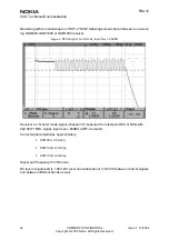
Transmitter troubleshooting diagrams
Figure 3: Transmitter troubleshooting
Yes
Yes
No
No
No
Yes
Yes
No
No
Yes
Yes
Yes
No
Yes
No
Yes
No
TX Troubleshooting
Check output signal level:
+32…[email protected](GSM900)
+29…[email protected] and 1880MHz
(GSM1800&1900)
OK?
Check
all power
levels,
OK?
TX OK
Tune
TX power
levels,
OK?
TX signal found?
Check output signal
on 500MHz span
Signal found on incorrect
frequency?
Synthesizer
troubleshooting
Check with RF probe signal level on
PA input: ~ -1…+5dBm
OK?
Helgo
troubleshooting
Start TX power level tuning and check tuned coefficient values:
Highest level ~0.655…0.831(GSM900); ~0.567…0.782(GSM1800&1900)
Lowest level ~0.166…0.196(GSM900); ~0.176…0.225(GSM1800&1900)
Base level ~0.137…0.166(GSM900); ~0.132…0.161(GSM1800&1900)
Major differences?
Tune TX coefficient
values
Check control voltage with
oscilloscope:
PA Ctrl voltage >1.5V peak
OK?
Check control loop
components
OK?
Replace Helgo
PA & Antenna Switch
troubleshooting
Replace faulty
components
Yes
No


