


RM-12
CCS Technical Documentation
Issue 1 11/2004
COMPANY CONFIDENTIAL
23
Copyright © 2004 Nokia. All Rights Reserved.
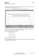
Figure 2:
GSM1900 RX I or Q signal (trace2), burst mode
GSM1900 receiver burst mode I or Q signal at ch 661 with input signal 1960.067MHz, level –
90 dBm at RF-connector.
Trace2: With wider time scaling both monitoring and own RX bursts are seen, 1
st
burst (shorter)
is monitoring and 2
nd
burst (longer) is own RX burst.
Trace1: External LNA VCC supply voltage at burst mode, input level –90 dBm. Measured from
testpoint LNA_VCC.


