


RM-12
CCS Technical Documentation
26
COMPANY CONFIDENTIAL
Issue 1 11/2004
Copyright © 2004 Nokia. All Rights Reserved.
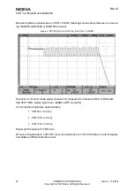
Troubleshooting diagram for GSM1800 receiver
Phone in “Continuous” mode, AGC setting “12”.
Figure 5: GSM1800 receiver troubleshooting
Apply –90dBm
1842.86771MHz signal
from generator to
antenna connector
Osilloscope at RX_I
signal 170mVpp DC
offset 1.35***
Frequency 67.7kHz
Spectrumanalyzer
Antenna Switch
output, GSM1800
-88dBm
Spectrumanalyzer
Antenna Switch
input –84dBm
Spectrumanalyzer
HELGO inputs
GSM1800 –88dBm
Oscilloscope
VANT_1…3 0V
Oscilloscope:Check
HELGO serial
interface (burst
mode)
Oscilloscope
VR1,3…6 2.7V
Check HELGO
serial interface
(burst mode)
* Spectrumanalyzer reading
with 1 kohm passive probe
(right value add +26dB)
All spectrumanalyzer
reading values are
measured with 1 kohm
passive probe (use
tweezers to connect the
probe ground to the nearest
PWB ground). Reading
value is represented without
+26 dB compensation.
Spectrumanalyzer
4G VCO output
3685.6MHz
~-30dBm*
Check HELGO
N500
Check
Baseband
Check
C809
Rx 1800 chain
functional
Check Z808,
L838,L839
Check
Baseband
Synthesizer
troubleshooting
Check HELGO
N500
Check Antenna
Switch Z800
*** DC-level of RXI/RXQ in
continuous mode will
decrase slowly. The original
level can be restored by
rewriting gain set
Yes
Yes
Yes
Yes
Yes
Yes
Yes
Yes
Yes
No
No
No
No
No
No
No
No
Note! Generator level can be set higher if needed.
Just note that levels will be different in whole chain
respectively.
Check SAW
filter output
Check Z808
No
Yes
X7100
N7300
Z7102,
L7105, L7106
Z7102
N7300
Z7100


