PAMS Technical Documentation
Trouble Shooting
NHM-3
2ULJLQDO
1RNLD0RELOH3KRQHV/WG
3DJH
3&16LJQDO3DWK
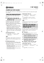
For easy error tracing it is important to know the signal path of the PCN receiver. The components can
be grouped into blocks and drawn as shown below.
6.3.1.
R
X
/
T
X
S
w
i
t
From the antenna pad (X901) the RF signal is lead to the RX/TX switch (Z900) via a mechanical
switch, the antenna connector (X900).
The RX/TX switch is normally open to the two RX outlets GSM_Rx and DCS_Rx. If no control voltage
is present at VC1 or VC2 the RX/TX switch will work as a diplexer and PCN signals pass to PCS_Rx
and EGSM signals to GSM_Rx.
From PCS_Rx the PCN signal is fed to the 1
st
PCN SAW filter via C913.
)URQWHQG
The PCN front-end consists mainly of two SAW filters (Z701 and Z702) and one LNA (V701) in-
between and finally one balun (T701). The SAW filters provides out-of-band blocking immunity, the
LNA provides front-end gain and the balun provides a balanced signal for Hagar (N500)
The signal-path is Through Z701 (In-band insertion-loss max 4dB), through the matching circuit (C702,
L701 and C703) and to the PCN LNA (V701, RFin).
The LNA has about 16.5 dB gain when it is on (LNA_P = 0 V and LNAB_D=2.7 V). If the signal applied
to the antenna-connector is more than –45dBm the AGC will gainstep the LNA (LNA_P = 2.7 V and
LNAB_G=0 V) which means the LNA Gain will now have negative gain (loss).
From the LNA (V701 RF out) the signal is lead through the LNA-output-matching-circuit (R701, L702
and C712), through the 2
nd
PCN SAW Z702 (In-band insertion-loss max 4dB) to the PCN balun T701.
From the balun the signal is balanced and is lead to Hagar (N500 IMP_PCN_RX and INM_PCN_RX).
+DJDU
The balanced RX signal is mixed with a signal from the local oscillator at the same frequency as the
wanted RX signal. After mixing the signal is converted to a singleended signal in the DtoS (Differential
to Singleended) amplifier. The signal is now filtered in a BIQUAD filter to provide channel separation,
amplified in the BB_Gain amplifier and DC compensated in DCN2.
2
2
2
2
INP_P_RX
INM_P_RX
RX/
T
X Swi
tch
RX
RX
TX
TX
INP_G_RX
INM_G_RX
DNC2
DNC2
LNA_P
RXQ
RXI
O
U
T_BB1_I
O
U
T_BB1_Q
I_
DCN2
_
I
I_
DCN2
_
Q
C
1_BB1_I
C
2_BB1_I
C
2_BB1_Q
C
1_BB1_Q
C
p_f
_I
C
m
_f
_I
C
p_f
_Q
C
m
_f
_Q
C
p_dt
os_I
Cm_
d
to
s
_
I
C
p_dt
os_Q
Cm_
d
to
s
_
Q
0-40dB
BB_Gain
0-40dB
BB_Gain
DtoS
DtoS
BIQUAD
BIQUAD
GSM
PCN
VRF_RX
VREF_RX
VB_EXT
RB_EXT
RF
Controls
8 / 18 dB
8 / 18 dB
SAW
SAW
SAW
SAW
LNA
LNA
Hagar
VRF_RX
VREF_RX
VREF
RXI
RXQ
Ant
enna connect
o
r
LNA_G
LNAB_D
LNAB_G