


36
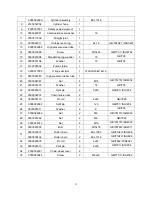
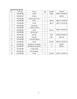
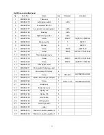
Easy worn parts list
No. Art
No.
Description
Qty.
Fig./Position Note
1
2000416003
Small wheels
2
Fig.7/1
Load wheel
2 0000027001
Bearing
4
Fig.6/11
Fig.7/4
Fig.12.1/2
Fig.12.2/2
Castor
Load wheel
One-stage mast
hydraulic system
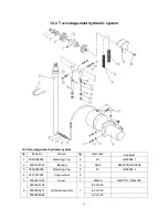
Two-stage mast
hydraulic system
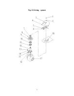
3 9000002141
Driving
wheel
1 Fig.19/21
Driving wheel
assembly
4 9000002143
Carbon
brush
4 Fig.19/41
Driving wheel
assembly
5 2040634001
Micro-switch
1 Fig.11/1
Electric parts and
components
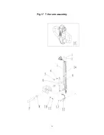
6 9000007398
Air
spring
1 Fig.17/6
Tiller arm assembly
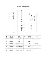
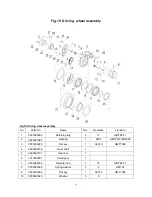
7
2000322002
Support ring for shaft
1
Fig.13/2
Cylinder assembly
8
0000022014
O seal ring
2
Fig.13/8
Cylinder assembly
9
0000022013
O seal ring
1
Fig.13/7
Cylinder assembly
10
2000322003
Support ring for hole
1
Fig.13/6
Cylinder assembly
11
2010322001
Y seal ring
1
Fig.13/5
Cylinder assembly
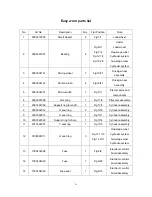
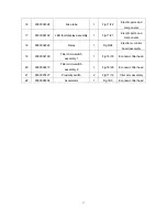
12
0000022011
O seal ring
3
Fig.12.1/12
Fig.12.2/11
One-stage mast
hydraulic system
Two-stage mast
hydraulic system
13 1000434008
Fuse
1 Fig.9/8
Electronic control
board assembly
14 1000434020
Fuse
1 Fig.9/25
Electronic control
board assembly
15 1000434040
Fuse
seat
1 Fig.9/16
Electronic control
board assembly
Summary of Contents for ECL 10
Page 28: ......
Page 31: ...3 Fig 1 Main components...
Page 36: ...8 Fig 5 Mast Assembly 5 1 Double Mast...
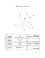
Page 38: ...10 Fig 6 Electronic control board assembly...
Page 41: ...13 Fig 8 Electric parts and components...
Page 53: ...25 Fig 14 Tiller arm assembly...
Page 55: ...27 Fig 15 Economic tiller head...
Page 60: ...32 Fig 18 Sticker for US...
Page 65: ...4 Fig 2 S ticker for US...
Page 67: ...6 Fig 3 Appearance...
Page 74: ...13 Fig 8 Mast assembly 8 1 Two stage mast...
Page 76: ...15 Fig 9 Electronic control board assembly...
Page 79: ...18 Fig 11 Electric parts and components...
Page 88: ...27 Fig 15 Driving system...
Page 91: ...30 Fig 17 T iller arm assembly...
Page 93: ...32 Fig 18 Economic tiller head...


