


15
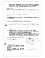
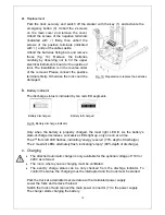
Charging is finished until the charging LED (fig.14,15) produces permanent green light.
The charger then goes into a floating mode to prevent the battery against damages.
Following table shows the function of the LED-status:
Table 3: LED-Status
LED- signal
Function
Red Battery
discharged
Orange Charging
Green Fully
charged
When charging is finished, disconnect the connector
from the socket and place it in the designated pocket.
6. REGULAR MAINTENANCE
Only qualified and trained personnel are allowed to
do maintenance on this truck.
Before maintaining, remove the load and lower the
forks to the lowest position.
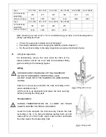
If you need to lift the truck, follow chapter 4 d by
using designated lashing or jacking equipment.
Before working, put safety devices (for instance
designated lift jacks, wedges or wooden blocks) under the truck to protect against
accidental lowering, movement or slipping.
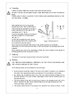
Please pay attention by maintain the tiller arm. The gas pressure spring is
pre-loaded by compression. Carelessness can cause injury.
Use approved and from your dealer released original spare parts.
Please consider that oil leakage of hydraulic fluid can cause failures and accidents.
It is allowed to adjust the pressure valve only from trained service technicians.
If you need to change the wheels, please follow the instructions above. The castors
must be round and they should have no abnormal abrasion.
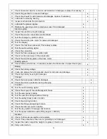
Check the items emphasized maintenance checklist.
a.
Maintenance checklist
Interval (Month)
Table 4: Maintenance checklist
1 3 6 12
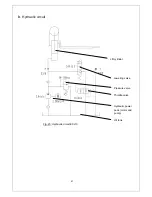
Hydraulic
1 Check the hydraulic cylinder, piston for damage noise and leakage
2 Check the hydraulic joints and hose for damage and leakage
3 Inspect the hydraulic oil level, refill if necessary
4 Refill the hydraulic oil ( 12 month or 1500 working hours)
5 Check and adjust the function of the pressure valve (1000 kg +0/ +10%)
Mechanical system
6 Inspect the forks for deformation and cracks
7 Check the chassis for deformation and cracks
8 Check if all screws are fixed
Fig. 15: LED- Status
Summary of Contents for ECL 10
Page 28: ......
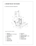
Page 31: ...3 Fig 1 Main components...
Page 36: ...8 Fig 5 Mast Assembly 5 1 Double Mast...
Page 38: ...10 Fig 6 Electronic control board assembly...
Page 41: ...13 Fig 8 Electric parts and components...
Page 53: ...25 Fig 14 Tiller arm assembly...
Page 55: ...27 Fig 15 Economic tiller head...
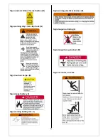
Page 60: ...32 Fig 18 Sticker for US...
Page 65: ...4 Fig 2 S ticker for US...
Page 67: ...6 Fig 3 Appearance...
Page 74: ...13 Fig 8 Mast assembly 8 1 Two stage mast...
Page 76: ...15 Fig 9 Electronic control board assembly...
Page 79: ...18 Fig 11 Electric parts and components...
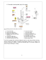
Page 88: ...27 Fig 15 Driving system...
Page 91: ...30 Fig 17 T iller arm assembly...
Page 93: ...32 Fig 18 Economic tiller head...


