


12
e.
Travelling
TRAVEL ON INCLINES ONLY WITH THE LOAD FACING UPHILL
.
DO NOT TRAVEL ON INCLINES MORE THAN SPECIFIED WITH THE TECHNICAL
DATA.
TRAVELLING IS ONLY ALLOWED IF THE FORKS ARE LOWERED DOWN TO THE
LIFTING POINT (<300MM).
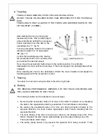
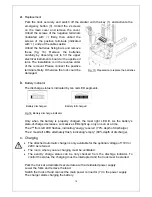
After starting the truck by turning the
inserted key to the “ON”- position (fig. 8;
and eventually by pulling the emergency
button carefully), move the tiller to the
operating zone (‘F’, fig.11).
Turn the accelerator button to the desired
direction forward ‘Fw.’ Or backwards
‘Bw.’(fig. 11).
Control the travelling speed by moving
the accelerator button (13) carefully until
you reached the desired speed.
If you move the accelerator button back to the neutral position, the controller
decelerates the truck until the truck stops. If the truck stopped, the parking brake will be
engaged.
Drive carefully the truck to the destination. Watch the route conditions and adjust the
travelling speed with the accelerator- button.
f.
Steering
You steer the truck by moving the tiller to the left or right side.
g.
Braking
THE BRAKING PERFORMANCE DEPENDS ONT THE TRACK CONDITONS AND
THE LOAD CONDITONS OF THE TRUCK
The braking function can be activated on several ways:
By moving the accelerator button (13) back to the initial ‘0’ position or by releasing
the button, the regenerative braking is activated. The truck brakes until it stops.
By moving the accelerator button (13) from one driving direction directly to the
opposite direction, the truck brakes regenerative until it starts travelling into the
opposite direction.
The truck brakes, if the tiller is moved up or down to the braking zones (‘B’). If the
tiller is released, the tiller moves automatically up to the upper baking zone (‘B’).
The truck brakes until it stops.
The safety (belly) button (12) prevents the operator from being crushed. If this
Fig.11: Operating direction
Summary of Contents for ECL 10
Page 28: ......
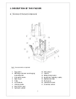
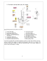
Page 31: ...3 Fig 1 Main components...
Page 36: ...8 Fig 5 Mast Assembly 5 1 Double Mast...
Page 38: ...10 Fig 6 Electronic control board assembly...
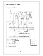
Page 41: ...13 Fig 8 Electric parts and components...
Page 53: ...25 Fig 14 Tiller arm assembly...
Page 55: ...27 Fig 15 Economic tiller head...
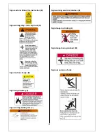
Page 60: ...32 Fig 18 Sticker for US...
Page 65: ...4 Fig 2 S ticker for US...
Page 67: ...6 Fig 3 Appearance...
Page 74: ...13 Fig 8 Mast assembly 8 1 Two stage mast...
Page 76: ...15 Fig 9 Electronic control board assembly...
Page 79: ...18 Fig 11 Electric parts and components...
Page 88: ...27 Fig 15 Driving system...
Page 91: ...30 Fig 17 T iller arm assembly...
Page 93: ...32 Fig 18 Economic tiller head...


