


14
a.
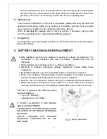
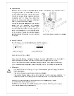
Replacement
Park the truck securely and switch off the stacker with the key (1) and activate the
emergency button (3). Unbolt the 2 screws
on the main cover and remove the cover.
Unbolt the screws of the negative terminals
(indicated with ‘-‘) firstly, then unbolt the
screws of the positive terminals (indicated
with ‘+’) and put the cables aside.
Unbolt the batteries fixing bars and remove
these (fig. 13). Remove the batteries
carefully by observing not to hit the upper
electrical instruments board or the upside oil
tank. The installation is in the reverse order
of the removal. Please connect the positive
terminals firstly. Otherwise the tuck could be
damaged.
b.
Battery Indicator
The discharge status is indicated by ten red LED segments.
Battery
discharged
Battery
full
charged
Fig.14: Battery discharge indicator
Only when the battery is properly charged, the most right LED lit. As the battery’s
state-of-charge decreases, successive LEDs light up, only one on at a time.
The 2
nd
from left LED flashes, indicating “energy reserve” (70% depth of discharge).
The 2 most left LEDs alternately flash, indicating “empty” (80% depth of discharge).
c.
Charging
The attached automatic charger is only available for the optional voltage of 110V or
220V as referred.
The room, where you are charging must be ventilated.
The exactly charge status can be only checked from the dischrge indicator. To
control the status, the charging must be interrupted and the truck must be started.
Park the truck at a dedicated secured area with a deidcated power supply.
Lower the forks and remove the load.
Switch the truck off and connect the main power connector (7) to the power supply.
The charger starts charging the battery.
Fig. 13: Preparation to replace the batteries
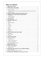
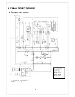
Summary of Contents for ECL 10
Page 28: ......
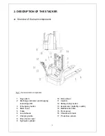
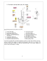
Page 31: ...3 Fig 1 Main components...
Page 36: ...8 Fig 5 Mast Assembly 5 1 Double Mast...
Page 38: ...10 Fig 6 Electronic control board assembly...
Page 41: ...13 Fig 8 Electric parts and components...
Page 53: ...25 Fig 14 Tiller arm assembly...
Page 55: ...27 Fig 15 Economic tiller head...
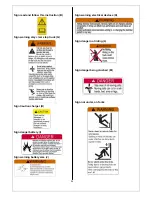
Page 60: ...32 Fig 18 Sticker for US...
Page 65: ...4 Fig 2 S ticker for US...
Page 67: ...6 Fig 3 Appearance...
Page 74: ...13 Fig 8 Mast assembly 8 1 Two stage mast...
Page 76: ...15 Fig 9 Electronic control board assembly...
Page 79: ...18 Fig 11 Electric parts and components...
Page 88: ...27 Fig 15 Driving system...
Page 91: ...30 Fig 17 T iller arm assembly...
Page 93: ...32 Fig 18 Economic tiller head...


