background image

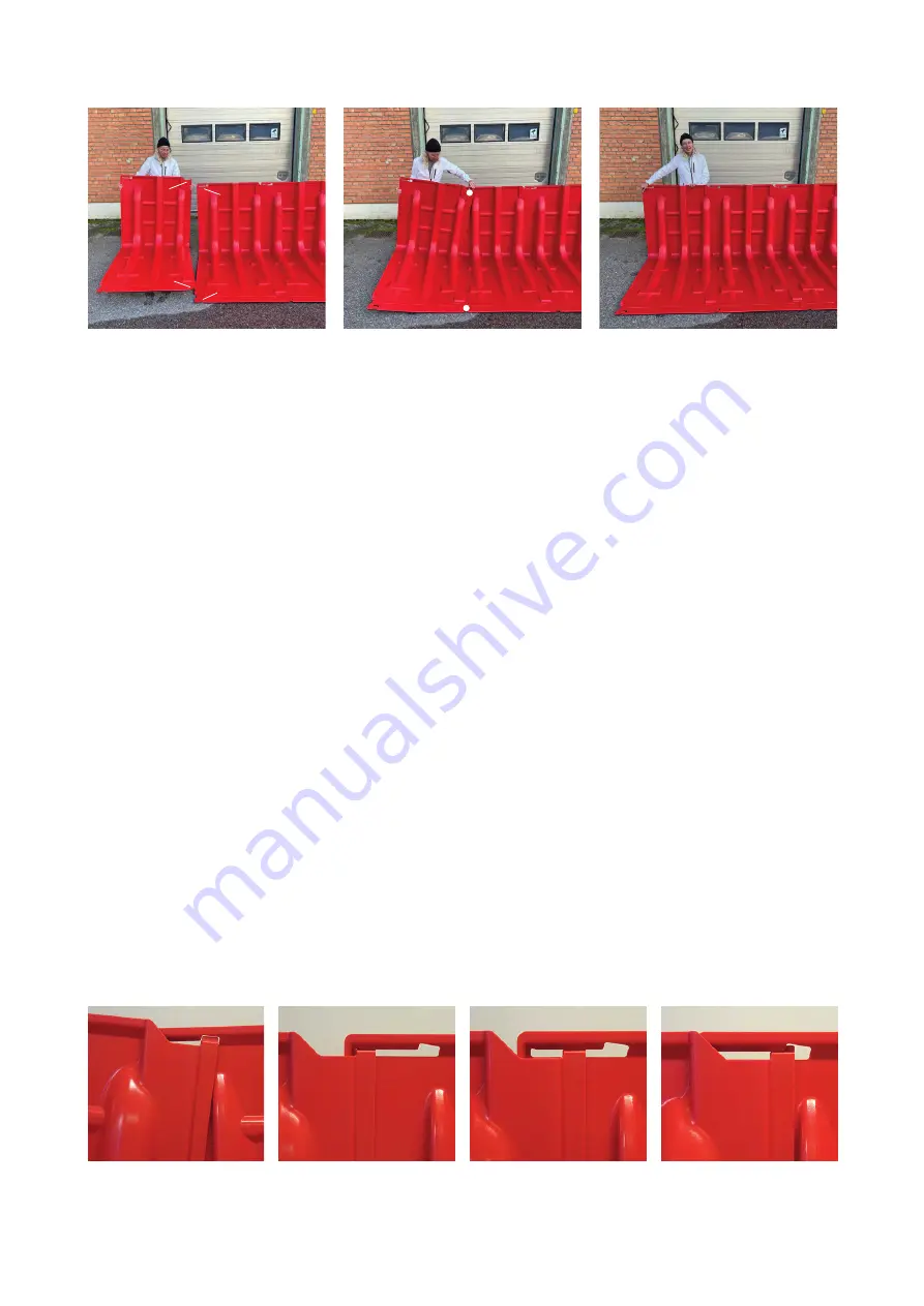
2. Lay out the boxes and connect them one by one

Start from the left (seen from the dry side) and connect the boxes one at a time to the previous 

one.


The boxes have a 

coupling mechanism

 (at the front) and a 

locking mechanism

 (at the 

top). Tip the box slightly forwards and connect it with the previous box by inserting the protruding 

”tongue” (on the far left) beneath the ”bridge” (on the right-hand side of the previous box).

Now lean the box a little to the side, press down its rear edge and insert the pin of the locking 

mechanism into the groove in the previous box. Use your foot to hold up the right side of the 

box to be able to use both hands for the coupling maneuver. Turn the box so that the pin ends 

up in the middle of the groove. This is the normal position.  However, the locking mechanism 

has a certain flexibility allowing the boxes to be /-2° against one another.

To help the sealing strip underneath create a tight seal against an uneven surface, you can 

place a weight on the front edge of each box, for example a stone or a sandbag. It can also 

be necessary to ballast the boxes in this way if there is a strong wind, before the water arrives. 

The boxwall is not very susceptible to winds coming from the front, but winds from behind 

will try to lift it.

Also when deploying a boxwall in deep water the boxes need to be ballasted from start to 

prevent them from floating. A difference in levels between the water in front of the boxwall 

and behind it is necessary to achieve the pressure difference that keeps the barrier in place.

If you want to improve the seal, you can cover the boxwall and its connections with a specific 

thin plastic sheeting, a liner. The sheeting for BW102 is 3.0 meters wide and can be fixed with 

clamps along the upper edge and with a line of gravel or sandbags on the ground in front of 

the front edge. By covering the boxwall with a plastic liner it can also be used on a much more 

uneven ground, as the liner is more flexible.

Assembly position 

2° in one direction 

Normal position 

2° in the other direction

4 (8)

NOAQ  BW102  1.0   201201

Locking mechanism

Coupling mechanism

Bridge

Tounge

Pin

Groove

Summary of Contents for Boxwall BW102

Page 1: ...all is so light that it can quickly be set up to protect buildings and other property against water damage and also to keep roads open A boxwall is designed for use on an even surface such as a paved street a concrete floor or a lawn A boxwall consists of sections boxes that are linked together by means of a simple manual operation No tools are needed The NOAQ Boxwall is also available in a lower ...

Page 2: ...g through the ground under the barrier Water may also come to the protected area as rain and through brooks which have been cut off by the barrier itself Therefore one or more pumps must always be put on the intended dry side of the barrier Sealing part Beneath the front edge of the boxwall is a sealing strip made of cellular rubber This keeps the leakage of water at the bottom to a minimum Anchor...

Page 3: ...oose sand and gravel must be brushed away from where the wall is to be erected The soles attached beneath each box have just as good a grip as the rubber soles on your shoes If there is sand on the road you run the risk of slipping and the same applies for the boxwall The coupling between the individual boxes has a built in flexibility of 2 which means a boxwall can be drawn in curves The curv rad...

Page 4: ...place a weight on the front edge of each box for example a stone or a sandbag It can also be necessary to ballast the boxes in this way if there is a strong wind before the water arrives The boxwall is not very susceptible to winds coming from the front but winds from behind will try to lift it Also when deploying a boxwall in deep water the boxes need to be ballasted from start to prevent them fr...

Page 5: ...ust be pumped clear with a pump If the ground slopes away from the flood e g on the crown of permanent embankments the water will run away without the need for pumps Having a working pump in place is extra important if the space between the barrier and the pro tected object is small for example when using a short boxwall in front of an entrance Without a pump even a small leakage may lead to fast ...

Page 6: ...e to each other facing upstream but do not try to connect them They will be anchored directly by the weight of the water entering upon them Behind this protective row of boxes a continuous boxwall may then be assembled When the boxwall is completed the front row of boxes can be removed This way the boxwall can be used to lead away watermasses in a controlled manner down the streets hereby reducing...

Page 7: ...ow all the boxes can be taken out first the 16 on the right then the 16 on the left The lid can also be removed but it is not necessary With the lid in place the short sides are also kept in place The short sides and the backside are fixed and cannot be removed 7 8 NOAQ BW102 1 0 201201 Also the loading of the case is made from the front first the 16 boxes that should stand to the left then the 16...

Page 8: ...are the same which means that all protective equipment must be used not only with good knowledge of its function and limitations but also with generally sound judgement Those who provide the equipment manufacturers resellers hirers etc can never accept liability for the actual use and any possible personal injury or damage to property that might arise Inspect all soft parts Damaged or worn sealing...

Reviews: