10
11
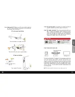
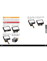
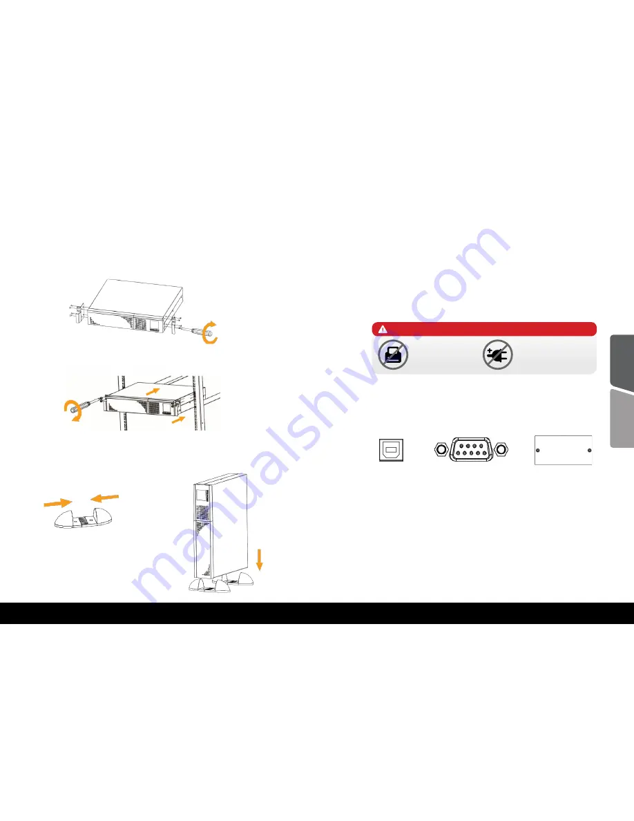
First fix the holders of the rack on the UPS.
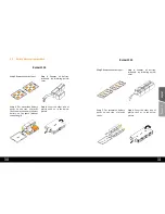
A. Rack - mount installation
B. Tower installation
Step 3.
Mounting the UPS:
Balder series UPS can be either displayed on
the desk or mounted in the 19” rack chassis. Please choose your
favourite way to position this UPS.
Then fix the UPS on the rack through the holders
First fix the holders to fit
the UPS.
Then put the UPS in place.
Step 4.
UPS input connection:
Plug the UPS into a two-pole, three-wire,
grounded receptacle only. Avoid using extension cords.
Step 5.
UPS output connection:
For socket-type outputs there two
kinds of output: programmable outlets and general outlets.
Please connect non-critical devices to the programmable
outlets and critical devices to the general outlets. During power
failure, you may extend the backup time to critical devices by
setting shorter backup time for non critical devices.
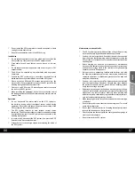
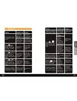
Do
NOT
plug
LASER
PRINTERS
into any of
the outlets.
Do
NOT
plug any
SURGE
STRIPS
into any of the
outlets.
CAUTION
Engli
sh
Română
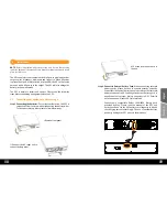
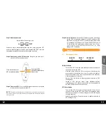
To allow for unattended UPS shutdown/start-up and status monitoring,
connect the communication cable one end to the USB/RS-232 port and
the other to the communication port of your PC. With the monitoring
software installed, you can schedule UPS shutdown/start-up and
monitor UPS status through PC. The UPS is equipped with a slot for
either SNMP or AS400 card. When installing either SNMP or AS400
card in the UPS, it will provide advanced communication and
monitoring options.
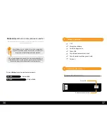
Communication port:
USB Port
RS-232 Port
Intelligent slot
Step 6.
Communication connection
NOTE:
USB port and RS-232 port can’t work at the same time.
Summary of Contents for Balder 1500
Page 37: ......


