Control System
20
Service Manual – SC351
Machine Enabling Push-Button Disassembly/Assembly (SW2)
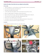
Disassembly
1
Drive the machine on a level floor. Make sure that the machine cannot move independently.
2 Turn the machine program selection knob to “0”
3 Disconnect the battery connector (red)
4 On the lower side of the handlebar with the control panel, unscrew the screws (A)
5 Move the upper side (B) of the handlebar with the control panel
6 Remove the screws (C) and move the lower side (D) of the handlebar from the frame (E)
7 Disconnect the connectors (F) of the brush enabling push-button (G)
8 Remove the screws (H) and remove the switch (G)
9 If necessary, remove from the housing the enabling push-button (I) of the switch (G)
10 If necessary, remove the brush levers (J) from the housing
Assembly
11 Assemble the components in the reverse order of disassembly
A
B
A
A
A
C
C
D
E
I
H
J
F
G
F
J
P100780

