background image

B.  Operation

After the engine has started, allow approximately 30 seconds for the engine to "warm up"  then advance the throttle to
operating speed.

Engage the clutch by pulling up on the switch lever (mounted on the handle).

Lower the burnishing head to the floor while moving the machine forward slowly.

CAUTION!   DO NOT RUN THE MACHINE WITHOUT MOVING THE MACHINE.  IF ALLOWED TO RUN IN ONE SPOT
DAMAGE TO THE FLOOR MAY OCCUR.

To stop burnishing, push down on handle raising the burnishing head off the floor and release the clutch switch lever.

NOTE:  This machine is equipped with SmartAir emission monitoring system and catalytic muffler.

Upon starting the engine, the GREEN LED will flash for 3 minutes during a  warm-up  period. After that time it will be on
steady unless a warning is being signaled. If the carbon monoxide in the exhaust is approaching a hazardous level the green
light will go out and the RED LED will start flashing. When the red light goes to STEADY RED it will shut the machine down
within 1 minute.

WARNING! Catalytic mufflers require a few minutes to warm up before effectively removing harmful emissions. Make
sure of proper ventilation during this warm-up period!

C.  Idling and Stopping the Machine

If for any reason the machine needs to idle for short periods (less than 3 minutes), simply raise the burnishing head and
release the clutch switch and move the throttle to the SLOW position. 

The SmartAir system will not allow the engine to

idle unnecessarily. After 2 minutes the GREEN LED will start flashing. In another 1 minute the engine will shut
down.

To stop the engine close the service valve on the fuel cylinder by turning it clockwise. (The engine will stop when the fuel in
the lines is used up.)  

After the engine stops, turn the key switch to "OFF" position. 

 Failing to turn the key OFF may

drain the battery.

D.  Installing/Changing Burnishing Pad

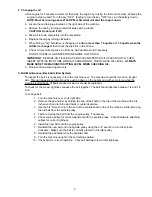
1. With engine OFF turn the machine over on the

 RIGHT

 side (the starter side).   This can be accomplished easily by

pushing down on the right handle grip with some force while the machine is tilted back.

2. Remove centering device (if used) and carefully pull old pad off the velcro pad holding material.

3.

CAREFULLY INSPECT THE PAD HOLDER FOR CRACKS OR DAMAGE!


Replace if necessary.

      NOTE:

 A damaged pad holder rotating at high speeds may be an extreme  hazard if it should come apart.

4. Pull center from new pad, center pad on pad holder and secure with centering device (if used) or tuck the center under

the plastic center ring.

5. Press pad onto velcro.

6. Return machine to upright position.

E.  Storage

Only authorized, trained personnel should have access to propane cylinders and machines.

1.

Remove propane fuel cylinder when not in use and store it outside in a storage cage in accordance with NFPA

Section 5 or Subsection 9.5.2 of CAN/CGA B149.2. Do not release or bleed propane inside of the building.

Please consult  your local Fire Marshal to insure that you are in compliance with local fire codes.

2. Store machine away from objects that may fall and damage it.

3. Never store machine or fuel cylinders near an open flame or heat producing devices.

4. Make sure machine is cleaned properly before storing.

5. Never store machines with cylinders installed, or spare cylinders, in an enclosed van or trailer.

F. Transportation

When transporting a propane powered burnisher with the fuel cylinder installed, the cylinder should be securely fastened
with the service valve closed and the machine should be secured in the vehicle. Any propane fuel cylinders not installed on a
machine should be securely fastened to avoid movement and damage. The service valves should be closed. Never store
machines with cylinders installed, or spare cylinders, in an enclosed van or trailer.

It is a good practice to check propane cylinders for overfilling before transporting them. If overfilled, correct  before loading
them in the vehicle by venting the excess propane outside in a safe area using the fixed liquid level gauge.

3

Summary of Contents for Kent 56010815

Page 1: ...er 56041489 SelectGloss 21 28PS OPERATOR MANUAL AND PARTS LIST OPERATOR MANUAL AND PARTS LIST OPERATOR MANUAL AND PARTS LIST OPERATOR MANUAL AND PARTS LIST OPERATOR MANUAL AND PARTS LIST Kent MODELS 56010815 56010816 ...

Page 2: ......

Page 3: ...________________________________________________ ADDRESS_________________________________________________________________________ CITY______________________________________STATE____________ZIP___________________ PHONE____________________________________CONTACT_______________________________ MACHINE SERIAL NUMBER__________________________________________________ ENGINE______________________________...

Page 4: ...e careful not to cross thread the Rego gas line coupling at the fuel cylinder Always store the fuel cylinder outside away from heat and direct sunlight Never leave the machine running unattended Always operate in a well ventilated area Catalytic mufflers need to warm up before they are effective Check pad holder for cracks each time the pad is changed Have the machine serviced by a certified techn...

Page 5: ...nattended These Propane Powered Burnishers are designed with the burnishing head offset to the right side to make it easier to burnish the floor close to the edge It is recommended to start burnishing on the right side of the isle turn and come back down the isle in the opposite direction overlapping the previous path slightly Continue this pattern until the floor area to be burnished has been cov...

Page 6: ...ad 3 E Storage 3 F Transportation 3 IV SCHEDULED MAINTENANCE 4 V GENERAL MAINTENANCE PROCEDURES A Fuel System 5 1 Adjusting the Regulator 2 Engine Dust Filter 3 Carburetor Air Filter 4 Fuel Hose and Connections B Engine Maintenance 5 6 1 Cooling Fins 2 Head Bolts 3 Changing Oil C Belt Maintenance 6 D Battery Maintenance and Replacement 7 E Adjusting the Handle 8 VI TROUBLESHOOTING 8 VII DRAWING AN...

Page 7: ... minimum requirements Even though the Kent propane powered burnishers meet the O S H A Time Weighted Average TWA standard for noise hearing protection is supplied with each machine and must be worn D Use and Care Your Kent propane powered burnisher is packaged with a detailed Operator s Manual Safety dictates that before using any new equipment operators read and understand the Operator s Manual W...

Page 8: ...Fill Fuel Cylinder Align the slot in the top flange of the cylinder with the locating pin on the machine Strap the safety fill cylinder in place by clamping the toggle assembly to the cylinder band Adjust the toggle assembly by screwing in or out in order to keep the tank firmly secured Connect the fuel hose coupling to the service valve by turning right clockwise HAND TIGHTEN ONLY Make sure coupl...

Page 9: ... OFF turn the machine over on the RIGHT side the starter side This can be accomplished easily by pushing down on the right handle grip with some force while the machine is tilted back 2 Remove centering device if used and carefully pull old pad off the velcro pad holding material 3 CAREFULLY INSPECT THE PAD HOLDER FOR CRACKS OR DAMAGE Replace if necessary NOTE A damaged pad holder rotating at high...

Page 10: ...ose Connections Inspect 2 2 Replace If Signs of Wear are Present 3 5 below Cooling Fins Clean 2 Burnishing Head Assembly Inspect 6 Pad Holder Inspect When Changing Pads Replace If Cracks Appear 2 below Bolts Connections Inspect 6 Tighten 6 Spark Plug Clean Replace 5 6 4 5 Battery Battery Cables Inspect 2 Exhaust Emissions Check 3 5 Check Adjust Valve Clearance 5 6 7 Retorque Heads 1 Perform after ...

Page 11: ...ilter element c Clean foam pre cleaner using the same procedure as 2 above d Clean filter seal making sure no dust is allowed in the carburetor inlet e Inspect paper element Replace if dirty bent or damaged f Install the clean paper element pre cleaner air filter cover and wing nut NOTE Failure to service the carburetor air cleaner may produce excessive carbon monoxide emissions and cause the Smar...

Page 12: ... necessary to turn the machine over The machine should be turned on its right side This can be easily accomplished by pushing down on the handle grip with some force while the machine is tilted back If badly cracked or worn it should be replaced To check for the proper tightness squeeze the belt together The belt should depress between 1 4 and 1 2 inch To change belt 1 Turn the machine over on its...

Page 13: ...t the BLACK negative battery cable last Dispose of old battery in the proper manner 7 Do not make direct contact between battery terminals as this can cause an explosion or fire Batteries should not be stored discharged Only adults should recharge batteries Keep charger away from children Use only the charger provided by the equip ment manufacturer Do not recharge batteries upside down Charging pr...

Page 14: ...Defective spark plug Defective coil Dirty air filter Low oil Fuse blown in SmartAir Wires broken or disconnected 3 Engine lacks power Leaking head gasket Insufficient vacuum Governor needs adjusting No compression worn rings Dirty air filters 4 Smell of burned rubber Belt out of adjustment 5 Machine vibrates Loose bolts Pad not centered 6 Machine Bogs Down when in use Operator bearing down too har...

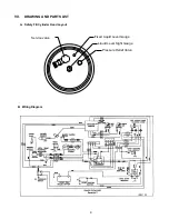
Page 15: ...Fixed Liquid Level Gauge Service valve Liquid Level Sight Gauge Pressure Relief Valve VII DRAWING AND PARTS LIST A Safety Fill Cylinder Head Layout 9 B Wiring Diagram ...

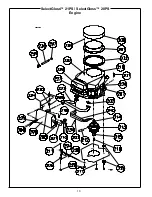
Page 16: ...10 SelectGloss 21PS SelectGloss 28PS Engine ...

Page 17: ...217 56630145 Washer Flat 5 16 3 218 56648218 Bolt Carriage 5 16 18 x 2 1 219 56648219 Stud Long 2 220 56622068 Precleaner Air 1 221 56648220 Deflector Exhaust 1 222 56648221 Stud Short 2 223 56648222 Manifold Long V Twin Kawasaki 1 224 56648223 Shield Manifold 1 225 56622112 Washer Star Lock 1 4 5 226 56648224 Bracket Muffler Kawasaki 1 227 56622069 Filter Air Kawasaki UL 1 228 56630136 Nut Lock 5...

Page 18: ...12 SelectGloss 21PS Deck Sub Assembly ...

Page 19: ...2 Washer Lock 5 16 1 313 56630136 Nut Lock 5 16 18 NC 3 314 56630122 Wheel w Bracket 5 2 315 56630080 Caster 2 1 2 Rear 3 4 Stem 1 316 56630130 Moulding 1 1 8 Black Bumper 5 ft 317 56630133 Rivet Pop 1 8 x 1 4 11 318 56622110 Wire Ground Hour Meter Assembly 1 319 56622133 Grommet 1 2 ID x 3 8 W x 1 D 1 320 56648237 Nut Hex 1 2 13 Jam 1 321 56622135 Bolt Hex 1 2 x 1 NC 4 322 56622122 Bolt Carriage ...

Page 20: ...14 SelectGloss 28PS Deck Sub Assembly ...

Page 21: ... NC 3 414 56630122 Wheel w Bracket 5 2 415 56630080 Caster 2 1 2 Rear 3 4 Stem 1 416 56622098 Wheel Block 2800 1 417 56630130 Moulding 1 1 8 Black Bumper 7 ft 418 56630133 Rivet Pop 1 8 x 1 4 11 419 56630139 Washer Flat 3 8 1 420 56622133 Grommet 1 2 ID x 3 8 W x 1 D 1 421 56630079 Retainer Pad Center Lok II 1 422 56648237 Nut Hex 1 2 13 Jam 1 423 56622126 Screw BH 5 16 18 x 1 1 2 3 424 56622135 B...

Page 22: ...16 SelectGloss 21PS SelectGloss 28PS Handle ...

Page 23: ...30106 Solenoid 12VDC Int Duty 1 134 56630107 Toggle Tank Strap 1 135 56622129 Bolt Carriage 3 8 16 x 1 1 4 5 136 56622120 Nut Lock 3 8 NC 5 137 56622107 Velcro Hook 1 w Adhesive 1 Yd 1 138 56630138 Washer Flat 1 4 2 139 56622078 Clamp Battery Asm 1 140 56622103 Insulator Rubber Battery Clamp 2 ITEM REF NO DESCRIPTION QTY 141 56622101 Hook Battery Clamp 2 142 56630173 Battery 12V Sealed Deka Type 1...

Page 24: ...Nilfisk Advance Inc 14600 21st Avenue North Plymouth MN 55447 3408 www nilfisk advance com Phone 800 989 2235 Fax 800 989 6566 1999 Nilfisk Advance Inc Plymouth MN 55447 3408 Printed in the U S A ...

Reviews: