Nilfisk-Advance Captor 4300 Quick Start Troubleshooting Manual Download Page 24


22

 - FORM NO. 56043093 / Captor

 4300, 4800, 5400

TROUBLESHOOTING GUIDE

Possible Symptom

1

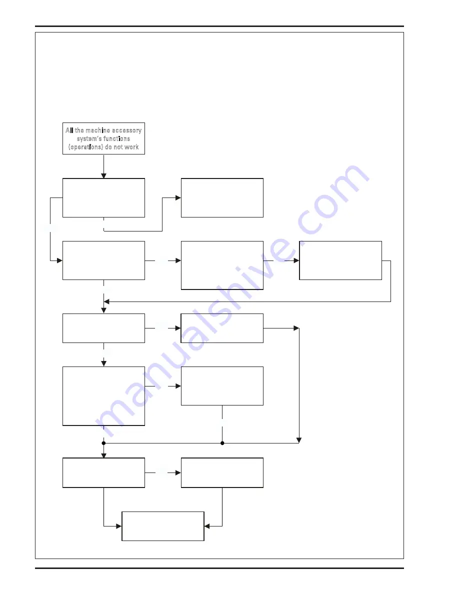
  All the machine accessory system’s functions (operations) do not work.  Example: no brush, broom, vacuum and hopper functions etc.

Part A: Electrical Control Circuit

Note: Do all testing with Key Switch ON.

All the machine accessory

system’s functions

(operations) do not work

When key is first turned

on do all the A2 display

panel lights momentarily

turn on?

Test for the 12V output from

A1 wires WHT/BRN & BLK

Check the power & commu-

nication inputs to A2

Test circuit continuity of

wires BRN/BLU & GRN/BLU

Test for 12V power input

wires WHT/BRN & BLK

Sub a new A2 Display Panel

Machine system fixed all

functions now operational

See Hydraulic Load Circuit

Part B

Repair or replace

defective wiring

Replace A1 Main

Controller

No

No

Test for the 12V power

input to A1, wires VIO &

BLK

Check for a defective F2

circuit breaker (15A)

An open in either the circuit

battery (pos.) VIO wire or BLK

battery (neg.) wire

No

Repair or replace defective

parts.

Do the A2 panel lights now

function?

No

Yes

Replace the A1 Controller

No

Yes

Yes

No

No

Yes

Summary of Contents for Captor 4300

Page 1: ... 56306052 56306053 56306054 56306055 56306056 56306057 56306058 56307251 56306182 56306183 56306184 56306185 56306186 56306187 56306188 56306189 56306190 All model numbers starting with 56306 and 56307 are manufactured with the 2007 certified engine 10 03 revised 6 12 Form Number 56043093 Quick Start Troubleshooting Manual Captor 4300 4800 5400 ...

Page 2: ... 59 ENGINE MAINTENANCE 59 CHECK ENGINE LIGHT TROUBLESHOOTING NON CERTIFIED TIER I 60 1 6L DTC CODES FOR TIER I 61 MISCELLANEOUS ENGINE SYSTEM INFORMATION 62 1 6L DTC CODES FOR TIER II 63 MISCELLANEOUS ENGINE SYSTEM INFORMATION 64 ENGINE FUEL SYSTEM FOR GASOLINE MODELS 64 66 HYDRAULIC SYSTEM 67 74 HYDRAULIC SYSTEM TROUBLESHOOTING 67 GENERAL HYDRAULIC SPECIFICATIONS TABLE 68 SETTING RELIEF VALVES 69...

Page 3: ...ix service sticker here NAME PLATE The Model Number and Serial Number of your machine are shown on the Nameplate on the machine This information is needed when ordering repair parts for the machine Use the space below to note the Model Number and Serial Number of your machine for future reference MODEL NUMBER SERIAL NUMBER HOPPER SAFETY SUPPORT WARNING Make sure the Hopper Safety Support KK is in ...

Page 4: ...e Manual WSM English French German 97897 01640 V1505 Kubota Diesel Engine Operator Manual English French German Italian Spanish 16622 8916 3 Available in electronic format only BOTTOM VIEW OF HYDROSTATIC PUMP GENERAL INFORMATION revised 7 08 The machine s drive propelling pump is manufactured with a selectable tow valve This valve prevents damage to the hydraulic system when the machine is being t...

Page 5: ...aught in moving parts Turn the key switch off O disconnect the battery and set the parking brake before servicing the machine Never work under a machine without safety blocks or stands to support the machine Do not dispense flammable cleaning agents operate the machine on or near these agents or operate in areas where flammable liquids exist Do not clean this machine with a pressure washer Keep th...

Page 6: ...m Hopper System Capacity 9 2 Cu Ft 261 L Lifting capacity 550 lbs 250kg Dump height variable Max 60 inches 152cm Dump height with door open 56 1 2 inches 143 5cm Dust Control System Filter type Pleated paper panel Filter dimension 3 3 16 x 20 x 27 8cm x 50 8cm x 68 5cm Filter media area 78 ft2 7 25m2 Steering System Type Power steering unit with rack and pinion Turns lock to lock right 4 3 8 Turns...

Page 7: ... Capacity 60 gal 227L 80 gal 303L 80 gal 303L Cleaning Rate per hour theory 75 700 ft2 7030m2 84 500 ft2 7 850m2 95 000 ft2 8 825m2 Sweeping path w side brooms 2 NA 62 in 158cm 62 in 158cm Sweeping path w side broom 1 51 in 130cm NA NA Sweeping rate per hour 134 600 ft2 12 500m2 163 700 ft2 15 210m2 163 700 ft2 15 210m2 Scrub Brush quantity 3 3 4 Scrub Brush diameter 15 in 38cm 17 in 43cm 14 in 36...

Page 8: ...ontrol filter and empty the hopper 3 Drain and flush the recovery tank 4 Flush the vacuum hose and squeegee by opening the recovery tank lid and running water down the pickup tube on the right side of the tank SERVICE NOTE Tip the recovery tank out and check the squeegee hose elbow below the tank to make sure it has flushed out completely 5 Remove and clean the squeegee tool adjust as needed 6 Rem...

Page 9: ... Replace the oil filter with every oil change TEMPERATURE RANGE OIL WEIGHT Above 60 F 15 C SAE 10W 30 Below 60 F 15 C SAE 5W 30 ENGINE OIL DIESEL Check the engine oil level when the machine is parked on a level surface and the engine is cool Change the engine oil after the first 35 hours of operation and every 150 hours after that Use CF CF 4 or CG 4 oil meeting API specifications and suited tempe...

Page 10: ...rain Products Operation and Maintenance manual for more detailed service data PSI manual number is 3610000 SPECIAL LIQUID PROPANE FUEL SYSTEM MAINTENANCE ON THE GM 1 6L ENGINE Every 150 hours inspect and drain any oil build up from the LP fuel system electronic pressure regulator EPR During the course of normal operation oils or heavy ends may build inside the chambers of the propane regulator The...

Page 11: ... Broom On Off will drift A B C 14 Side Broom On Off 15 Scrub System Raise Lower and auto scrubbing functions 16 Scrub Brush pressure settings 1 2 3 A B 17 Squeegee System Raise Lower and Auto Lift in Reverse A B 18 Vacuum Performance Sealed water lift 22 and 1 inch open hole adapter 20 inches C L W 19 Solution Control On Off and Flow Volume Min Max C L 20 Perform the machine self diagnostic test s...

Page 12: ...e Diesel Fuel Tank Filter Lines C L 52 LP Tank Hoses Fittings L 53 LP Fuel Filter SVR Life 1500 Hrs L Replace 54 LP Fuel Regulator Lock Off Valve Hoses L 55 Diesel Glow Plug Indicator Light Hard Starting Replace 56 Diesel Fuel Filter Yearly L Replace 57 Scrub Brushes check for wear and rotate D M W 58 Scrub Deck Skirts D M W 59 Solution Solenoid Valve D L W 60 Solution Flow Control Valve and Linka...

Page 13: ...FORM NO 56043093 Captor 4300 4800 5400 11 THIS PAGE IS INTENTIONALLY BLANK ...

Page 14: ...se 8 Engine Air Filter 9 Left Engine Compartment Access Panel 10 Main Broom Left Access Door 11 Battery 12 Hopper Lid Prop Rod 13 Front Wheel 14 Left Side Broom 15 Hopper Lid Latch 16 Headlights 17 Right Side Broom 18 Hopper Cover 19 Dust Control Filter 20 Dust Control Shaker Assembly KNOW YOUR MACHINE 1 2 3 4 5 6 7 9 8 10 6 13 14 15 16 17 18 19 20 21 12 22 23 24 44 46 47 45 48 49 ...

Page 15: ...Tip Out Latches 35 Hydraulic Charge Oil Filter 36 Hydraulic Reservoir In Tank Return Oil Filter 37 Right Engine Compartment Access Panel 38 Main Broom Right Access Door 39 Access Door Latch 40 Skirt Assembly 41 Inline Solution Filter 42 Solution Tank Drain Hose 43 Rear Roller Bumper 44 Jacking Location 45 Engine Oil Dipstick 46 Air Filter Service Indicator 47 Fuel Filter Gas Models 48 Recovery Tan...

Page 16: ...oom down on indicator turn off approximately two seconds 6 Release the side broom down on switch 7 The control will now activate each output in sequence and perform the tests mentioned above 8 If no abnormal conditions are detected the display will now show Go to step 10 9 If abnormal output conditions were detected the display will now show the error code s see Main Control Error Code Display Des...

Page 17: ...hart 17 Shaker relay coil circuit open See shaker will not run troubleshooting flow chart 18 Back up alarm circuit short Check alarm and wiring 19 Back up alarm circuit current too high Check alarm and wiring 20 Back up alarm circuit open Check alarm and wiring 21 Horn relay coil circuit short Check for wiring problems at the K1 relay Check K4 coil resistance if below 315 ohms replace 22 Horn rela...

Page 18: ... Replace coil Shorted Coil 47 S9 dust control circuit open Check for open in coil wiring Check for 12V at the L9 coil wire colors ORG BRN YEL 48 S7 scrub motors circuit short Check for wiring problems at the L7 coil Check L7 coil resistance if below 7 ohms Replace 49 S7 scrub motors circuit current too high Same as Error 48 Replace coil Shorted Coil 50 S7 scrub motors circuit open Check for open i...

Page 19: ...for open in coil wiring Check for 12V at the L1 coil wire colors ORG BLU WHT 69 S2 squeegee direction circuit short Check for wiring problems at the L2 coil Check L2 coil resistance if below 7 ohms Replace 70 S2 squeegee direction circuit current too high Same as Error 69 Replace coil Shorted Coil 71 S2 squeegee direction circuit open Check for open in coil wiring Check for 12V at the L2 coil wire...

Page 20: ...pper will not lower 36 37 Hopper dump door will not open 38 Hopper dump door will not close 39 Hopper dump door will not open or close 40 Scrub System 41 50 Scrub deck will not lower in pressure setting 1 41 42 Scrub deck will not lower in pressure setting 2 43 44 Scrub deck will not lower in pressure setting 3 45 46 Scrub deck will not raise 47 48 Scrub brush motors will not operate 49 50 Solutio...

Page 21: ...N Indicator O Main Broom ON Indicator P Light Sensor Q Shaker Switch Shaker Indicator left Dust Filter Plugged Indicator right R Open Dump Door Switch Open Dump Door Indicator S Hopper Open Indicator T Hopper Overtemp Indicator U Close Dump Door Switch Close Dump Door Indicator V Lower Hopper Switch Lower Hopper Indicator W Raise Hopper Switch Raise Hopper Indicator X Dust Control Switch Dust Cont...

Page 22: ...be programmed for its neutral position and dead band setting follow instructions shown on this page Repair or replace relay or wir ing Is there 12 volts at the BLU PNK Replace engine fuse box start relay Loca tion of fuse box on top of engine No No At the K4 relay do you have 12 volts at the BLU PNK Yes No Engine will still not crank No Yes No Engine will not crank Is the neutral indicator light o...

Page 23: ...12V at the X9 harness connector location by engine starter pin A wire color pink Repair or replace wiring back to the F3 circuit breaker Check the continuity of the F3 circuit breaker Replace the F1 5 Amp fuse Select fuel type Gasoline LP Check for 12V at fuel pump Check fuel pump F4 fuse 15 Amp Replace F4 fuse 15 Amp Check fuel filter pickup Check fuel pump output Repair or replace Engine still w...

Page 24: ...V output from A1 wires WHT BRN BLK Check the power commu nication inputs to A2 Test circuit continuity of wires BRN BLU GRN BLU Test for 12V power input wires WHT BRN BLK Sub a new A2 Display Panel Machine system fixed all functions now operational See Hydraulic Load Circuit Part B Repair or replace defective wiring Replace A1 Main Controller No No Test for the 12V power input to A1 wires VIO BLK ...

Page 25: ... coupler Yes No Hydraulic Accessories Work Do some accessory functions work If so see chart belowfor appropriate pump circuit Pump circuit 2 poor or no performance of steering system dump door hop per lift engine fan dust control and side brooms Failure of the propulsion coupler input to the front accessory pump repair or replace the faulty pump Pump circuit 3 poor or no performance of scrub motor...

Page 26: ...d delay the activation of turning on the auto sweep and scrub functions when the drive pedal is moved out of an excessively wide programmed neutral range Machine drive auto function does not work Place the pedal in forward or reverse position Check on the A1 control board Is the green neutral indicator light on Is the hopper yellow indicator light on at the A1 board Adjust or replace magnetic swit...

Page 27: ...vated the vacuum motor will turn on when the engine is started Hydraulic motor s will not stop running Is the indicator light OFF at the A2 display panel for the malfunctioning motor Replace the A2 touch pad Locate the malfunctioning motors hydraulic cartridge valve clean or replace See hydraulic system s troubleshooting section for locations Yes No Is the green indicator light for the malfunction...

Page 28: ...nloading pressure setting to low for application No wheel drive in either direction Check that pump bypass valve tow valve is in correct position Check connection of foot pedal linkage cable assembly to propulsion pump arm Worn propulsion pump test output oil volume with a flow meter Defective propulsion pump charge circuit Test its relief valve pressure setting 75 150 psi Worn or damaged wheel dr...

Page 29: ...G SYSTEM TROUBLESHOOTING OVERVIEW See Figure 1 A hydraulic steering unit with the steering wheel mounted to it controls the rack cylinder The steering unit runs off the middle gear pump of the auxiliary pump assembly The oil flows through a priority divider built into the pressure relief block assembly that divides the pump output and reduces the oil flow to 1 75 GPM for the steering system There ...

Page 30: ...icator light on Check the adjustment operation of the S16 broom switch Switch continuity is open with broom lever lowered Check for 12V at the L6 sole noid coil wire colors GRN GRA ORG Check both wires for continuity Repair or replace defective wire s Does broom run Check the L6 coil resistance it should read 7 9 ohms Replace L6 coil checks open or shorted Does broom run See Part B main broom moto...

Page 31: ...spool valve L6 Does motor operate Replace motor No No No No Yes Inspect the main broom for possible mechanical bind ing damaged broom lug inserts and debris wrapped around broom or broom motor Remove debris and make any repairs or replace damaged parts Does the main broom turn Yes Main broom will not turn See troubleshooting sec tion titled No hydraulic accessories work Remove and disassemble L6 b...

Page 32: ...h located on the A2 display panel Is its green indicator light on Substitute a new A2 display panel Do side brooms operate Check for 12 volts at L10 side broom motors coil Wire colors ORG BRN BLK Repair or replace L10 coil wiring Do the side broom motors operate Check L10 coil resistance 9 ohm Repair or replace L10 coil Do the side broom motors operate See Hydraulic side broom troubleshooting sect...

Page 33: ...activated Side brooms will not turn Clean and repair motors Do they turn Replace defective spool valve L10 Do the side broom motors run Repair or replace side broom motors Remove and disassemble L10 spool valve cartridge Inspect clean and reinstall Do the side broom motors run Yes Do some pump circuit 2 funtion work steering engine fan dust control Inspect for possible debris wrapped around motor ...

Page 34: ... Substitute a new A2 display panel Do the brooms now raise or lower Press the side broom OFF raise button and check on the A1 control board to see if its green relay indicator light comes on Replace the A1 control board Do brooms now raise or lower Test for 12V at the M4 actuator motor To lower wire colors WHT RED To raise BLK WHT Repair or replace defective connector and or wiring Do brooms raise...

Page 35: ...tor will not run Press the dust control switch located on the A2 display panel Is its green indicator light on Substitute a new A2 display panel Does impeller operate Check for 12V at L9 impeller motor coil Wire colors ORG BRN YEL Repair or replace L9 coil wiring Does impeller motor operate Check L9 coil resistance 9 ohm Repair or replace L9 coil Does impeller motor operate See Hydraulic impeller ...

Page 36: ...e engine running 2400 rpm Also dust control switch must be activated on the display panel and the drive pedal must be activated Dust control impeller will not run Remove and disassemble L9 spool valve cartridge inspect clean and reinstall Does the impeller motor run Replace defective spool valve L9 located on impeller motor Does it operate Repair or replace impeller motor No No ...

Page 37: ...air or replace wiring to coil Does shaker motor operate Check the K3 coil resistance should measure 370 Ohms or 10 Replace the defective K3 relay Does shaker motor operate Yes Yes Yes No No No Press shaker switch button and check on the A1 control board to see if the shaker relay green indicator light is on Replace A1 control board Does shaker motor operate No Yes Check for 12V at the shaker motor...

Page 38: ...splay panel Substitute a new A2 display panel Does the hopper raise Check for 12 volts at L13 hopper raise coil Wire colors ORG RED GRY Repair or replace L13 coil wiring Does the hopper raise Check for coil resistance at L13 9 ohm Repair or replace L13 coil Does the hopper raise See Hydraulic hopper lift troubleshooting section Part B Yes Yes Yes No No No Press and hold hopper raise button On the ...

Page 39: ...der Do some pump circuit 2 function work steering engine fan dust control No Repair or replace damaged parts Does the hopper raise See hydraulic load trouble shooting No accessories work No No Remove and disassemble L13 hopper raise Spool valve cartridge inspect clean and reinstall Does the hopper raise Yes Replace defective spool valve L13 hopper raise Does the hopper rasie Is the hopper over its...

Page 40: ...ht on Substitute a new A2 display panel Does the hopper lower Check for 12 volts at L14 hopper lower coil Wire colors ORG YEL RED Repair or replace L14 coil wiring Does the hopper lower Check for coil resistance at L14 9 ohm Repair or replace L14 coil Does the hopper lower See Hydraulic hopper lower troubleshooting section Part B Yes Yes Yes No No No Press and hold hopper lower button is the green...

Page 41: ... Repair or replace damaged parts Does the hopper lower Remove and disassemble L14 hopper lower Spool valve cartridge inspect clean and reinstall Does the hopper lower Replace defective spool valve L14 hopper lower Does the hopper lower No Inspect for possible mechanical binding of Hopper linkage Hopper cylinder Hopper will not lower Replace hydraulic hopper cylinder No No No Yes ...

Page 42: ...troubleshooting section Part B Repair or replace L11 coil No No Yes No Yes Replace the A1 Control board No Yes Yes Repair or replace L11 coil wiring No Yes Substitute a new A2 Display panel Does dump door operate Repair or replace S12 switch wiring Does door open Yes Yes No Dump Door will not open Check if the hopper raise indicator light is flashing on A2 panel Check continuity and adjustment of ...

Page 43: ...color ORN BLK WHT Check for coil resistance at L12 9 ohm See hydraulic dump door troubleshooting section Part B Check continuity and adjustment of hopper raise magnetic switch S12 Note Switch will check open when hopper is raised Repair or replace L12 coil Does the door operate No No Yes Press and hold hopper door close switch Is its green indicator light on Check S12 switch wiring for a short No ...

Page 44: ...or cylinder Do some pump circuit 2 functions work Steering engine fan dust control and side broom motor s No Yes Repair or replace dump door dump door linkage dump door cylinder Does the door function See hydraulic load trou bleshooting section titled No Accessories work No Remove and disassemble L11 door open L12 door closed Spool valve cartridge inspect clean and reinstall Does the door function...

Page 45: ...s green indicator light on Substitute a new A2 display panel Does the deck lower Check for 12 volts at coil L4 ORG YEL BLU Repair or replace defective coil wiring Does the deck lower Check for coil resistance at L4 9 ohm Replace defective coil Does the deck lower See Hydraulic scrub deck troubleshooting section Part B position 1 Yes Yes Yes No No No Press scrub off switch then scrub decrease switc...

Page 46: ...00 rpm Repair or replace damaged parts Does scrub deck lower Remove and disassemble L4 scrub deck spool valve cartridge inspect clean and reinstall Does scrub deck lower Replace defective spool valve L4 Does scrub deck function No Inspect for possible mechanical binding of Scrub deck mount linkage Scrub deck cylinder Check deck pressure with a scale 1 120 lbs 2 237 lbs 3 385 lbs Replace cylinder N...

Page 47: ...the display Is its green indicator light on Substitute a new A2 display panel Does the deck lower Check for 12 volts at coils L3 ORG BRN L5 ORG WHT VIO L15 ORG GRN VIO Repair or replace defective coil wiring Does the deck lower Check for coil resistance at L3 L5 L15 9 ohm Replace defective coil s Does the deck lower See Hydraulic scrub deck troubleshoot ing section Part B position 2 Yes Yes Yes No...

Page 48: ...read 160 PSI 5 In 2 and 0 in 1 No Yes Install a pressure gauge to the bottom of the scrub deck lift cylinder Does the pressure read 160 PSI Replace defective spool valve L15 Does scrub deck function Replace pressure valve 2 160 PSI reset Does the deck function No No Check deck pressure with a scale 1 120 lbs 2 237 lbs 3 385 lbs Replace cylinder No Does the deck function in pressure setting 1 Scrub...

Page 49: ... in the display Is its green indicator light on Substitute a new A2 display panel Does the deck lower Check for 12 volts at coils L3 ORG BRN L4 ORG YEL BLU L5 ORG WHT VIO Repair or replace defective coil wiring Does the deck lower Check for coil resistance at L3 L4 L5 9 ohm Replace defective coil s Does the deck lower See Hydraulic scrub deck trouble shooting section Part B position 3 Yes Yes Yes ...

Page 50: ...and reinstall Does scrub deck function in setting 2 Install a pressure gauge to the top of the scrub deck lift cylinder XT4 Does the pressure read 160 PSI 5 In 3 and 0 in 1 No Install a pressure gauge to the bottom of the scrub deck lift cylinder Does the pressure read 0 PSI No Check deck pressure with a scale 1 120 lbs 2 237 lbs 3 385 lbs Replace cylinder No Does the deck function in pressure set...

Page 51: ...new A2 display panel Does the scrub deck raise Press the scrub deck off but ton On the A1 board is the S3 green relay indicator light on Repair or replace BRN L3 coil wire Short to frame ground Does the scrub deck raise Replace A1 control board Does the scrub deck raise Check for 12 volts at L3 squeegee deck coil Wire colors ORG BRN See Hydraulic scrub deck troubleshooting section Part B Yes Yes Y...

Page 52: ...e inspect clean and reinstall Does scrub deck function Replace defective cartridge Does the scrub deck raise No Yes Inspect for possible mechanical binding of scrub deck mount linkage scrub deck cylinder Insert a pressure gauge at the XT3 pressure fitting Test the 8 relief valve found on squeegee brush cylinder valve block 800 psi No Adjust clean or replace 8 relief valve Does scrub deck function ...

Page 53: ...ub decrease switch along with moving the foot pedal Check on the A1 board to see if the green S7 motor relay light is on Repair or replace defective coil wiring Do the motors operate Check for 12 volts at coil L7 ORG ORG BLU Replace the defective L7 coil Do the motors operate Yes Yes Yes No No No Press scrub decrease switch on the display Is its green indicator light on Sub a new A2 display panel ...

Page 54: ...egee in their lowered position Insert a pressure gauge at the XT3 pressure fitting Does the 1B relief valve found on main relief valve block open at 2400 PSI No Check for debris wrapped around the motor shafts Repair or replace individual defective motor Do the motors run No Remove and disassemble L7 scrub motor spool valve cartridges Inspect clean and reinstall Do the motors turn Replace defectiv...

Page 55: ...el Does the solution solenoid operate Check for 12V at the L16 sole noid coil wire colors ORG YEL GRN Repair or replace wiring to the solenoid valve Does the solution solenoid operate Check the L16 solenoid coil resistance it should read 7 9 Ohms Replace the L16 coil as it tests either open or shorted Yes Yes Yes No No No Press the solution button and check on the A1 control board to see if the gr...

Page 56: ...ts green A2 indicator light on On the A2 board is the recovery tank full light on Locate the indicator switch plug and jump out the machine harness wires GRY YEL and BLK Does the light go off Repair machine harness wires to A1 board GRN YEL BLK Does the light go off Press the squeegee button along with moving the foot pedal On the A1 board is the S8 vacuum relay light on Yes Yes No No No Replace t...

Page 57: ...r closed Squeegee switch must be activated on the display panel and the foot pedal moved into forward or reverse Continued from previous page Check for 12 volts at the L8 coil wire colors ORG BLU Repair or replace wiring to coils Does vacuum motor operate See Hydraulic vacuum motor troubleshooting section Part B Yes No Check for coil resistance at L8 valve 9 ohm Replace defective coil Does vacuum ...

Page 58: ...nd reinstall Does motor operate Replace defective spool valve L8 Does motor operate Replace motor No Yes Inspect for possible mechanical binding or debris in the vacuum motor impeller assembly Does the vacuum motor operate Does the main broom on pump circuit 1 work No See hydraulic load trou bleshooting section title No accessories work No Yes Yes No No No Poor pick up performance Inspect for poss...

Page 59: ...t on Substitute a new A2 display panel Does squeegee operate Check for 12 volts inputs at L1 and L2 coils wire colors ORG L1 and L2 L1 BLU WHT L2 ORG RED Repair or replace wiring to coils Does squeegee oper ate Check for coil resistance at L1 and L2 9 ohm Replace defective coil Does squeegee operate See Hydraulic squeegee troubleshooting section Part B Yes Yes Yes No No No Press the squeegee butto...

Page 60: ...eegee spool valve cartridge inspect clean and reinstall Does squeegee function Squeegee will not reach its correct position Inspect for possible mechanical binding of Squeegee mount linkage Squeegee cylinder Replace defective spool valve L1 and L12 Does squeegee function Replace cylinder No Yes Inspect for possible mechanical binding of Squeegee mount linkage Squeegee cylinder Insert a pressure ga...

Page 61: ...ition Timing Fixed controlled by engine ECM Engine Rotation CCW flywheel end Valve lifters Hydraulic Oil Capacity 3 7 qts 3 5L with Oil Filter Oil Pressure 21 PSI minimum with engine hot at idle Cooling System 3 5 qts Engine Only ROUTINE ENGINE MAINTENANCE Keep the fuel tank filled This helps to reduce condensation and moisture entering the fuel system gasoline Make daily checks of the engine oil ...

Page 62: ...cate the 4 way ECM communication test port which is a part of the engine wiring harness location in area of engine starter 3 Next remove the test port protective cap See Figure 1 Insert a suitable jumper wire across pin A orange wire pin D black green wire 4 Turn the engine key switch to the on position and observe the indicator lights special error code flashing sequence See PSI s 1 6L Emission C...

Page 63: ...2 Crank Sync Noise 1C4 58 DTC 612 FPP Low Voltage 1C4 136 DTC 143 Never Crank Sync at Start 1C4 62 DTC 613 FPP Higher Than IVS Limit 1C4 140 DTC 211 C L Multiplier High LPG 1C4 64 DTC 614 FPP Lower Than IVS Limit 1C4 142 DTC 212 HO2S Open Inactive 1C4 68 DTC 631 TPS 1 Signal Voltage High 1C4 144 DTC 221 C L Multiplier High Gasoline 1C4 72 DTC 632 TPS 1 Signal Voltage Low 1C4 148 DTC 222 C L Multip...

Page 64: ... ECM communication test port which is a part of the engine wiring harness 3 Next remove the test port protective cap See Figure 1 5 Insert a suitable jumper wire across pin 1 black green wire pin 4 orange wire Blink Code Function Although the DST Diagnostic Service Tool software is considered a required tool to access the DTC codes codes may be retrieved without a laptop computer using the blink c...

Page 65: ... Inactive 724 10 1171 LPG Pressure Higher Than Expected 520260 0 154 EGO 2 Open Inactive 520208 10 1172 LPG Pressure Lower Than Expected 520260 1 171 Adaptive Learn High Gasoline 520200 0 1173 EPR Comm Lost 520260 31 172 Adaptive Learn Low Gasoline 520200 1 1174 EPR Voltage Supply High 520260 3 182 Fuel Temp Gasoline Low Voltage 174 4 1175 EPR Voltage Supply Low 520260 4 183 Fuel Temp Gasoline Hig...

Page 66: ...ngine fuel system its high fuel delivery pressure must be relieved First relieve the built up trapped fuel pressure by safely discharging it at the engine fuel injector fuel rail bleeder fitting Schrader valve GM 1 6L GASOLINE FUEL SYSTEM DESCRIPTION TIER II CERTIFIED This engine is equipped with a fuel injector rail that does not have a pressure regulator Fuel pressure for this engine is regulate...

Page 67: ...ump relay coil B F3 15 Amp Fuse for input power to the alternator C F4 15 Amp Fuse for Fuel Pump D F2 20 Amp Fuse for ECM input alternator power relay coil E Relay Fuel Pump F Engine Starter Relay G Power Relay Alternator FRONT B C G F A D Engine Fuse Box E FIGURE 3 FIGURE 2 Non Certified TIER I All 1 6L Models revised 7 08 ...

Page 68: ...66 FORM NO 56043093 Captor 4300 4800 5400 ENGINE SYSTEM FIGURE 4 TIER II revised 7 08 ...

Page 69: ...es and there will be variations due to manufacturer tolerances and system oil temperature If any reading varies greater than 20 there will be a noticeable loss of performance and should be corrected TEST PORT NOMINAL PRESSURE READINGS see Figure 1 Insert pressure gauge see Figure 1 into one of the three test ports Run engine in high idle position Allow oil to warm up The bypass pressure is the pre...

Page 70: ...in 5 2 2400 300 2400 Scrub 1 Std 180 grit brush on sealed concrete 4 5 cu in 5 2 270 650 2400 Scrub 2 Std 180 grit brush on sealed concrete 4 5 cu in 5 2 265 1000 2400 Scrub 3 Std 180 grit brush on sealed concrete 4 5 cu in 5 2 255 1350 2400 Scrub 1 Black pad on sealed concrete 4 5 cu in 5 2 270 800 2400 Scrub 2 Black pad on sealed concrete 4 5 cu in 5 2 265 1200 2400 Scrub 3 Black pad on sealed c...

Page 71: ...nergize L6 main broom solenoid using the adapter cord The pump circuit 1 will be in overload use caution not to leave in this position for a long period may cause damage Observe the pressure gauge and adjust accordingly Relief should be at 2700psi Loosen Lock nut turn Adjustment Screw CCW to decrease pressure CW to increase FRONT Relief Valve 2700 PSI vacuum fan main broom 1 1A 1B Relief Valve 240...

Page 72: ...brooms Cap the right side broom drive motor inlet hose 37 outside hose at motor Finish raising the hopper and engage the safety latch Carefully reopen the door Open engine hopper door panel to access pump relief valve block assembly Insert hydraulic test gauge 3000psi to the XT 2 test port To adjust the hydraulic oil must be warm and engine in high speed 2400rpm Energize L10 side broom solenoid us...

Page 73: ...alve wire colors ORG and BLU WHT Insert hydraulic test gauge 1000psi to the XT 3 test port To adjust the hydraulic oil must be warm and engine in high speed 2400rpm Energize L1 demand valve solenoid using the adapter cord The pump circuit 3 will be in overload use caution not to leave in this position for a long period may cause damage Observe the pressure gauge and adjust accordingly Relief shoul...

Page 74: ...72 FORM NO 56043093 Captor 4300 4800 5400 HYDRUALIC SYSTEM ...

Page 75: ...FORM NO 56043093 Captor 4300 4800 5400 73 HYDRAULIC SYSTEM ...

Page 76: ...r Assembly 9 1 Reservoir Assembly 10 3 Scrub Motor Assembly 11 1 Squeegee Fan Motor Assembly 12 1 Engine Fan Motor Assembly 13 1 Impeller Motor Assembly 14 1 Wheel Motor Assembly 15 1 Main Broom Motor Assembly 16 2 Side Broom Motor Assembly 17 1 Squeegee Brush Cylinder Valve Block Assembly 18 1 Manifold Assembly 19 1 Main Relief and Broom Scrub Motors Valve Block Assy 20 1 Hopper and Side Broom Va...

Page 77: ... in neutral K6 Relay SPDT AXP EDS L16 Solution Valve M2 Shaker Motor M3 Fuel Pump Gas only M4 Actuator Side Broom M6 Pump Assy AXP EDS P6 Gauge Combination R2 Drive Pedal Sensor R4 Flow Position Sensor AXP EDS S1 Switch Ignition S3 Switch Low LP Pressure S6 Switch Hydraulic Filter S8 Switch Recovery Full S9 Switch Solution Empty S12 Switch Hopper Interlock S16 Switch Main Broom Hydraulic Valve Tru...

Page 78: ...d Valve S3 L4 Scrub Down Valve S4 L5 Scrub Down Valve S5 L6 Main Broom Valve S6 L7 Scrub Brush Valve S7 L8 Vac Fan Valve S8 L9 Dust Control Valve S9 L10 Side Broom Valve S10 L11 Dump Door Open Valve S11 L12 Dump Door Close Valve S12 L13 Hopper Raise Valve S13 L14 Hopper Lower Valve S14 Item Description WIRING DIAGRAM SCHEMATIC FOR Gasoline Petrol and LPG Captor CR 1100 series 56304xxx Models TIER ...

Page 79: ...FORM NO 56043093 Captor 4300 4800 5400 77 ELECTRICAL SYSTEM SCHEMATIC FOR Captor CR 1100 series 56304xxx Models TIER I Revised 11 04 ...

Page 80: ...RN GRN WHT GRN RED WHT GRN PINK PURPLE BLK RED BLK RED PINK GRA BLU BLU BLK GRN YEL GRA BLU PINK TAN PINK YEL PINK YEL BLU PINK BLK GRN YEL VIO BLU GRA BRN GRA BRN BLK GRA GRA BRN BLK BLU ORN RED VIO GRA VIO BLK RED YEL BLK ORN PINK GRA BLU BLU BLK C X2 F F F9 CIRCUIT BREAKER 60 AMP 1 2 D D M M5 FUEL PUMP R1 SENDER OIL PRESSURE 1 2 A A F8 CIRCUIT BREAKER 10 A 1 2 F4 CIRCUIT BREAKER 15 AMP 1 2 K6 R...

Page 81: ...DECAL PART NO 56306084 2 REFERENCE LADDER DIAGRAM 56306080 NOTES CLOSED WHEN BROOM IS DOWN COOLANT TEMPERATURE OUTPUT THROTTLE INPUT 12V FOR HIGH SPEED GM ENGINE SYSTEM REFERENCE E CONTROLS INC DRAWING NO E1737100 AND E1737200 GASOLINE SENSOR IGN SWITCH INPUT FUEL PUMP MIL OUTPUT ALT EXCITE START COMMAND CAN CAN FUEL PUMP 10 19 06 A 03130 10 19 06 WGL 10 19 06 10 19 06 JH ATH B B B AXP SYSTEM NOTE...

Page 82: ... PLUGGED FUNCTION SCRUB ON SCRUB 1 SCRUB 2 SCRUB 3 SCRUB UP SQUEEGEE UP MAIN BROOM SIDE BROOM DUST CONTROL HOPPER UP HOPPER DOWN DUMP DOOR OPEN DUMP DOOR CLOSE SQUEEGEE DOWN VAC FAN J2 16 J2 9 DIESEL MODE SELECT J2 23 J2 1 FROM GLOW PLUGS J1 25 THROTTLE ACTUATOR WIRING A B EXTEND FOR IDLE A B RETRACT FOR RUN OPTIONAL J1 11 J1 22 J1 10 J1 21 J1 9 J1 4 J1 20 J1 8 J1 7 J1 18 J1 6 J1 19 J1 17 J1 5 J1 ...

Page 83: ...16 PINK DK GREEN 16 D C B A SHD 12162859 BLACK 18 PURPLE WHITE 18 WHITE PURPLE 18 CRANK_PSI_1P6 TAN ORANGE 18 BOSCH THROTTLE PINK WHITE 18 LT BLUE DK BLUE 18 PURPLE LT BLUE 18 LT GREEN RED 18 BLK LT GREEN 18 1 4 5 6 3 2 RED 14 RED TAN 14 WHITE BLUE 18 POWER_RELAY 85 86 87 30 PINK DK GREEN 16 F3 15A PINK DK GREEN 16 PINK DK GREEN 16 RED 12 RED 16 ALTERNATOR RED 16 ALTERNATOR B A BATT 2 RED 12 FUEL_...

Page 84: ...IL 1 COIL 2 UNUSED UNUSED UNUSED INJ 7 UNUSED UNUSED ECM Detail RELAY FUSED POWER X7 GROUND FUEL PUMP AUX IN PU1 AUX IN PU2 AUX IN PD2 F E D C B A PINK DK GREEN 16 BLACK 16 PINK YELLOW 16 DK BLUE YELLOW 18 YELLOW DK BLUE 18 BLACK WHITE 18 X8 BLUE PINK 18 GRAY DK BLUE 18 TAN BROWN 18 YELLOW LT GREEN 18 TAN DK GREEN 18 LT BLUE WHITE 18 X9 BLUE WHITE 18 PURPLE DK BLUE 18 LT BLUE BLK 18 BLACK LT GREEN...

Page 85: ...TOR 2 INJECTOR 3 INJECTOR 4 FUEL PUMP RELAY FUEL PUMP BATT GROUND ALTERNATOR ALTERNATOR ALTERNATOR DIAGNOSTIC CONNECTOR CONNECTOR 1 VEHICLE INTERFACE CONNECTORS CONNECTOR 2 B L H J I E D F G A K C EGO 2 EGO 1 ECT BOSCH_TMAP OIL PRESSURE SENSOR IGNITION COIL CRANK SENSOR GROUND POWERRELAY IGNITION STARTER RELAY STARTER SOLENOID ECM STARTER VSW GCP 90 WAY CONNECTOR Q ...

Page 86: ...TT GROUND ALTERNATOR ALTERNATOR ALTERNATOR DIAGNOSTIC CONNECTOR CONNECTOR 1 VEHICLE INTERFACE CONNECTORS CONNECTOR 2 N L H J I E D F G A K C EGO 2 EGO 1 ECT BOSCH_TMAP OIL PRESSURE SENSOR IGNITION COIL CRANK SENSOR GROUND EPR IGNITION STARTER RELAY STARTER SOLENOID ECM STARTER VSW M LOCKOFF P ENGINE HARNESS for GM 1 6L LPG Propane Tier II ...

Page 87: ... S R CAN1 P CAN1 N M L K J FUEL SELECT H MIL OUTPUT G START COMMAND F E FUEL PUMP D FUEL PUMP C ALT EXCITE B IGN SWITCH INPUT A X1 GRA BLU 18 1 TAN 18 1 S R P N M L THROTTLE INPUT K 12V FOR HIGH SPEED H G COOLANT TEMP OUTPUT F E D C B A X2 WHT GRN 18 1 GRN RED 18 1 GRN WHT 18 1 BLK GRN 18 1 D C B A X78 GASOLINE MODELS ONLY DIAGNOSTIC CONNECTOR Machine Harness Connectors ECM Harness Connectors Wiri...

Page 88: ...86 FORM NO 56043093 Captor 4300 4800 5400 ELECTRICAL SYSTEM THIS PAGE IS INTENTIONALLY BLANK ...

Page 89: ... on position 4 Continue to hold the vacuum squeegee switch until all indicators except the vacuum squeegee indicator turn off approximately two seconds 5 Release the vacuum squeegee switch 6 The status display will now show a number from 1 to 9 Pressing and releasing the vacuum squeegee switch will increase the displayed value until 9 is reached The next press will return to 1 Each increment repre...

Page 90: ...key switch to the on position 4 Continue to hold the shaker switch until all indicators except the shaker indicator turn off approximately two seconds 5 Release the shaker switch 6 The status display will now show a number from 1 to 9 Pressing and releasing the shaker switch will increase the displayed value until 9 is reached The next press will return to 1 Each increment represents two seconds w...

Page 91: ... 3 While holding the hopper door close switch turn the main power key switch to the on position 4 Continue to hold the hopper door close switch until all indicators except the hopper door close indicator turn off approximately two seconds 5 Release the hopper door close switch 6 The status display will now show a number from 1 to 9 Pressing and releasing the hopper door close switch will increase ...

Page 92: ...hen the foot pedal is moved from the neutral position These functions are triggered via a position sensor mounted on the hydrostat Whenever adjustments are made to the hydrostat unit the neutral position will need to be programmed Also the neutral dead band sensitivity can be adjusted if necessary To set the neutral position and adjust the neutral dead band perform the following steps 1 Turn the m...

Page 93: ... 8 The new setting will be saved and will remain in effect until it is changed again Side Broom Mode Control FACTORY DEFAULT 1 always turns on with main broom RANGE 0 2 The side brooms on the Captor are programmed to always come on when the main broom is first activated If this is not desired the operating mode of the side booms can be changed To select the operating mode 1 Turn the main power key...

Page 94: ... indicators turn off approximately two seconds 5 Release both switches 6 The status display will now show a number from 0 to 2 Pressing and releasing the dust control switch will increase the displayed value until 2 is reached The next press will return to 0 If 0 is selected the dust control will not come on with the main broom It will be manual control only If 1 is selected the dust control will ...

Page 95: ...FACTORY DEFAULT 2 no change RANGE 0 2 The dust control on the Captor can be programmed to turn on or off or stay in its current state when the hopper is raised for dumping To select the operating mode 1 Turn the main power key switch to the off position 2 Press and hold the dust control and the scrub pressure decrease switches 3 While holding both switches turn the main power key switch to the on ...

Page 96: ...th switches until all indicators except the engine speed and scrub off indicators turn off approximately two seconds 5 Release both switches 6 The status display will now show a 0 or a 1 Pressing and releasing the engine speed switch will alternate between the two If 0 is selected the automatic engine speed control is disabled turned off If 1 is selected the automatic engine speed control is enabl...

Page 97: ...wo codes 6 and 18 would be displayed is as follows The display will show E followed by a brief blank period The display will show 0 followed by a brief blank period The display will show 6 followed by a slightly longer blank period The display will show E followed by a brief blank period The display will show 1 followed by a brief blank period The display will show 8 followed by a long blank perio...

Page 98: ...ut J1 11 BLU WHT Demand valve S1 DC Voltage 14V B 13 5 14 5V w engine running Moving forward and scrub raising and or squeegee raising and or squeegee lowering Output J1 12 GRA VIO Side broom actuator M4 common DC Voltage 14V See comments 13 5 14 5V w engine running Measure between J1 23 and J1 12 when raising side brooms Measure between J1 35 and J1 12 when lowering side brooms Output J1 13 GRA W...

Page 99: ...or fuel line is disconnected Input J2 4 YEL VIO Hopper fire switch S7 DC Voltage 14V B 13 5 14 5V w engine running On when internal temperature of hopper is too high Input J2 5 YEL WHT Hydraulic filter switch S6 DC Voltage 14V B 13 5 14 5V w engine running On when filter is too dirty or plugged Input J2 6 WHT GRA Dust control filter switch S5 DC Voltage 14V B 13 5 14 5V w engine running On when ho...

Page 100: ...ine running 13 5 14 5V w engine running Input J2 22 PINK Ignition input DC Voltage 14V B Ground 12 12 6V w o engine running 13 5 14 5V w engine running J2 23 Empty Switch Display Panel Assembly J3 1 Empty Output J3 2 RED YEL Light sensor DC Voltage Between 0 and 5V B Ground 0 5V J3 3 ORN BRN Not used J3 4 Empty Input Output J3 5 BRN BLU To control box assembly Serial clock signal 0 to 5V B Ground ...

Page 101: ... EDS Control Box Assembly H Dual 12V Detergent Pumps NN AXP EDS System Supervisor Mode Display Icon RR AXP EDS Detergent ON OFF Switch SS Detergent Ratio Increment increase Switch TT Detergent Ratio Decrement decrease Switch UU AXP EDS System Display Panel VV Main Solution Pump Flow Indicator bar Display 40 100 WW Detergent Ratio Active Status Call Out Display XX AXP EDS System Error Code E1 Panel...

Page 102: ...100 FORM NO 56043093 Captor 4300 4800 5400 AXP EDS SYSTEM revised 12 08 ...

Page 103: ...cartridge When the detergent level is nearing the bottom of this slot it is time to refill or replace the cartridge General Use The detergent AXP EDS system is enabled when the Key Switch MM is turned on and reverts to the last state Chem On or Chem Off it was in prior to the last power down The current Solution Flow Rate VV and the last used Detergent Ratio WW if in Chem On state are displayed Th...

Page 104: ...ontinued Main Solution System Components 4 Cable Solution Control Lever 13 Solution Filter Elbow Fitting 14 Solution Sensor Potentiometer connected to solution control lever 21 Solution System Pump Assembly 25 Detergent Pump Output Delivery Hose 27 Solution Detergent Tee Fitting revised 12 08 ...

Page 105: ...8 26 RED 14 1 RED 14 1 VIO GRA 18 1 BLK 18 37 BLK 18 36 BLK 18 35 GRA BRN 18 2 BLK 18 35 YEL GRN 18 4 BLU ORN 18 1 BLK GRA 18 1 VIO YEL 18 2 GRA BRN 18 4 BLK GRA 18 1 GRA BRN 18 3 BLK 18 36 BLU ORN 18 1 X81 X167 X169 R4 F8 F9 X7 K6 SP16 SP17 to Solution Pump to Solution Control Pot to Ground to AXP Control Box to Circuit Breakers to Main Harness Pos to Relay 30 to A1 Control Box to Relay revised 1...

Page 106: ...L Available dilution rates 21 1 26 1 32 1 50 1 64 1 100 1 128 1 150 1 200 1 256 1 300 1 AXP EDS display panel solution flow rate table Flow Solution volume 40 1 20 gal min 4 54L min 50 1 41 gal min 5 33L min 60 1 85 gal min 7 00L min 70 2 09 gal min 7 91L min 80 2 46 gal min 9 31L min 90 2 76 gal min 10 44L min 100 3 10 gal min 11 73L min revised 12 08 ...

Page 107: ......

Page 108: ......

Reviews: