background image

ITALIANO

MANUALE DI ASSISTENZA

34

909 6424 000(3)2007-12

BR 601 / BR 651 / BR 751 / BR 751 C

IMPIANTO DI SPAZZOLATURA

SMONTAGGIO/MONTAGGIO DELL'ATTUATORE DI SOLLEVAMENTO/ABBASSAMENTO DELLA 

TESTATA PORTASPAZZOLE

Smontaggio

Portare la macchina nella zona di smaltimento designata, quindi svuotare il serbatoio dell'acqua di recupero (58) con il tubo 

(22).

Svuotare il serbatoio della soluzione detergente/acqua di lavaggio (59) con il rubinetto (36).
Portare la macchina su un terreno pianeggiante.
Portare la chiave di avviamento (12) su "0".
Con cautela sollevare completamente il gruppo serbatoi (60), per accedere alle batterie.
Scollegare il connettore delle batterie (63).
Rimuovere la testata (vedere procedura al paragrafo specifico).
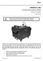
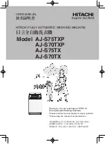
Rimuovere i dadi (A), quindi rimuovere con cautela il coperchio (B).
Spostare con cautela il pannello dei componenti elettrici (C) e scollegare il connettore (D) dell'attuatore di sollevamento/
abbassamento della testata.
Rimuovere la vite di fissaggio inferiore (E) dell'attuatore (F).
Rimuovere la vite (G).
Rimuovere l'attuatore (F).

Montaggio

Montare i componenti nell'ordine inverso rispetto allo smontaggio.

S301333

1.

2.
3.
4.
5.
6.
7.
8.
9.

10.
11.
12.

13.

Summary of Contents for BR 601

Page 1: ...BR 601 BR 651 BR 751 BR751 C ITALIANO MANUALE DI ASSISTENZA ENGLISH SERVICE MANUAL 909 6424 000 3 2007 12 ...

Page 2: ......

Page 3: ...LLO E SOSTITUZIONE DEI CARBONCINI DEI MOTORI DELLE SPAZZOLE A DISCO 28 CONTROLLO E SOSTITUZIONE DEI CARBONCINI DEI MOTORI DELLE SPAZZOLE A RULLO 28 SMONTAGGIO MONTAGGIO DEI MOTORI DELLE SPAZZOLE A DISCO PORTAFELTRO 29 SMONTAGGIO MONTAGGIO DEI MOTORI DELLE SPAZZOLE A RULLO 30 CONTROLLO SOSTITUZIONE TENSIONAMENTO DELLE CINGHIE DI TRASMISSIONE DAI MOTORI ALLE SPAZZOLE A RULLO 32 SMONTAGGIO MONTAGGIO ...

Page 4: ...ONE Macchine dopo gennaio 2007 62 SMONTAGGIO MONTAGGIO DEL MOTORE DELL IMPIANTO DI TRAZIONE Macchine fino a Gennaio 2007 64 SMONTAGGIO MONTAGGIO DEL MOTORE DELL IMPIANTO DI TRAZIONE E RELATIVI CUSCINETTI E GUARNIZIONI Macchine dopo gennaio 2007 65 SMONTAGGIO MONTAGGIO DEL PEDALE DI MARCIA AVANTI RETROMARCIA 68 CONTROLLO E REGOLAZIONE DEL POTENZIOMETRO DEL PEDALE DI MARCIA AVANTI RETROMARCIA 69 CON...

Page 5: ...rter siano chiusi La chiave di avviamento sia disinserita La macchina sia saldamente legata al mezzo di trasporto ALTRI MANUALI DISPONIBILI Presso Nilfisk Literature Service Department sono disponibili i seguenti manuali Manuale operatore BR 601 BR 651 BR 751 BR 751C 909 6160 000 Catalogo ricambi BR 601 BR 651 BR 751 BR 751C 909 6161 000 Istruzioni di montaggio Kit fermo coperchio serbatoio 909 68...

Page 6: ...seguito vengono descritte avvertenze e attenzioni specifiche per evidenziare i potenziali pericoli di danneggiamento della macchina e delle persone PERICOLO Prima di eseguire qualsiasi intervento di manutenzione riparazione portare la macchina su un terreno pianeggiante rimuovere la chiave di avviamento e scollegare la batteria Questa macchina deve essere usata solo da personale propriamente addes...

Page 7: ...ta macchina fare attenzione a salvaguardare l incolumità di persone e cose La temperatura di immagazzinamento della macchina deve essere compresa tra 0 C e 40 C La temperatura d uso della macchina deve essere compresa tra 0 C e 40 C 32 F e 104 F L umidità deve essere compresa tra il 30 e il 95 Proteggere sempre la macchina da sole pioggia e altre intemperie sia in stato di funzionamento che di fer...

Page 8: ...za massima di lavoro 2 1 Pressione acustica all orecchio dell operatore ISO 11201 ISO 4871 LpA 60 8 dB A 3dB A Potenza acustica emessa dalla macchina ISO 3744 ISO 4871 LwA 82 4 dB A Livello di vibrazioni trasmesse alle braccia dell operatore ISO 5349 1 0 23 7 5 m s2 9 05 295 3 in s2 Livello di vibrazioni trasmesse al corpo dell operatore ISO 2631 1 1 2 m s2 47 24 in s2 Batterie Cassonetto da 24 V ...

Page 9: ...motore spazzola portafeltro 400 W 0 54 hp Velocità di rotazione spazzole portafeltro 190 giri min Pressione spazzole portafeltro con pressione supplementare disinserita 30 kg 66 lbs Pressione spazzole portafeltro con pressione supplementare inserita 50 kg 110 lbs CARATTERISTICHE TECNICHE CON TESTATA PORTASPAZZOLE A RULLO Descrizione BR 751C Dimensioni spazzola a rullo diametro x lunghezza 145 x 69...

Page 10: ...424 000 3 2007 12 BR 601 BR 651 BR 751 BR 751 C INFORMAZIONI GENERALI INGOMBRI BR 601 1450 mm 57 0 in 830 mm 32 6 in 1250 mm 49 2 in 658 mm 26 in BR601 INGOMBRI BR 651 681 5 mm 26 8 in 830 mm 32 6 in 1450 mm 57 0 in 1250 mm 49 2 in BR651 ...

Page 11: ...01 BR 651 BR 751 BR 751 C 909 6424 000 3 2007 12 INFORMAZIONI GENERALI INGOMBRI BR 751 758 mm 30 in 1450 mm 57 0 in 1250 mm 49 2 in 860 mm 33 9 in BR751 INGOMBRI BR 751 C 758 mm 30 in 1450 mm 57 0 in 1250 mm 49 2 in 860 mm 33 9 in BR751C ...

Page 12: ...rnaliera dopo l uso della macchina Settimanale Semestrale Annuale Pulizia del tergitore Pulizia delle spazzole Pulizia dei serbatoi e della griglia di aspirazione con galleggiante Carica delle batterie Controllo e sostituzione delle gomme del tergitore Controllo dei flap laterali Pulizia del filtro della soluzione detergente Controllo del livello del liquido delle batterie WET Controllo del serrag...

Page 13: ...zione detergente acqua di lavaggio opzionale Tubo di scarico acqua di recupero Tubo di aspirazione tergitore Tergitore Ruote paracolpi Ruote di appoggio tergitore Volantini di fissaggio tergitore Volantino di regolazione bilanciamento tergitore Gomma anteriore tergitore Gomma posteriore tergitore 1 2 3 4 5 6 7 8 9 10 11 12 13 14 15 16 17 18 19 20 21 22 23 24 25 26 27 28 29 30 Gancio di fissaggio g...

Page 14: ...e flap Spazzola a rullo Sportelli spazzola a rullo Pomelli di fissaggio sportelli Cassetto rifiuti spazzola a rullo 74 75 76 77 78 79 80 81 82 83 84 85 86 87 88 89 90 Maniglia cassetto rifiuti Coperchio componenti elettrici Dadi di fissaggio coperchio Caricabatterie opzionale Selettore tipo di batterie WET o GEL Fusibile F2 di protezione scheda elettronica impianto di trazione 60 A Fusibile F3 di ...

Page 15: ...09 6424 000 3 2007 12 13 MANUTENZIONE NOMENCLATURA DELLA MACCHINA Continua 33 34 35 13 14 42 32 15 19 20 25 18 16 21 43 25 29 30 26 27 31 24 26 27 25 23 28 17 37 38 40 39 41a 18 36 43 25 22 44 44 44 3 2 6 5 4 7 7c 7b 7a 8 9 10 10a 10b 11 12 1 18 16 39 41b S301637 ...

Page 16: ...ITALIANO MANUALE DI ASSISTENZA 14 909 6424 000 3 2007 12 BR 601 BR 651 BR 751 BR 751 C MANUTENZIONE NOMENCLATURA DELLA MACCHINA Continua S301638 S301317 S301639 ...

Page 17: ...MANUALE DI ASSISTENZA ITALIANO BR 601 BR 651 BR 751 BR 751 C 909 6424 000 3 2007 12 15 MANUTENZIONE NOMENCLATURA DELLA MACCHINA Continua S301619 ...

Page 18: ...macchina operando come indicato nel Manuale operatore fino all esaurimento della soluzione detergente acqua di lavaggio contenuta nel serbatoio Rimuovere l asta di sostegno 57 e chiudere il coperchio 56 Pulire il filtro della soluzione detergente acqua di lavaggio vedere la procedura seguente PULIZIA DEL FILTRO DELLA SOLUZIONE DETERGENTE ACQUA DI LAVAGGIO Portare la macchina su un terreno pianeggi...

Page 19: ...Con il cric sollevare la macchina di circa 2 cm 0 78 in Rimuovere la vite C e recuperare la rondella D Rimuovere la ruota destra E Rimuovere le viti F Spostare in avanti il supporto G sganciando il ritegno H dalla vite I Scollegare i tubi J e K dai relativi raccordi L Scollegare il tubo M dal pressostato N tirandolo Scollegare i connettori O dell elettrovalvola P e del pressostato Recuperare il gr...

Page 20: ...909 6424 000 3 2007 12 BR 601 BR 651 BR 751 BR 751 C IMPIANTO DI ALIMENTAZIONE SOLUZIONE DETERGENTE SMONTAGGIO MONTAGGIO ELETTROVALVOLA RUBINETTO GRUPPO FILTRO DELL IMPIANTO DELLA SOLUZIONE DETERGENTE ACQUA DI LAVAGGIO Continua S301321 ...

Page 21: ...valvola è rotta oppure il collegamento elettrico è interrotto sostituire l elettrovalvola ripristinare il collegamento elettrico Presenza di detriti nel serbatoio della soluzione detergente acqua di lavaggio che ostruiscono il foro di uscita pulire il serbatoio Presenza di detriti nella tubazione della soluzione detergente acqua di lavaggio che ne ostruiscono flusso pulire la tubazione La soluzion...

Page 22: ...avaggio 59 con il rubinetto 36 Portare la macchina su un terreno pianeggiante Portare la chiave di avviamento 12 su 0 Con cautela sollevare completamente il gruppo serbatoi 60 Svitare il raccordo A e rimuovere il tubo B dal serbatoio del detersivo C Rimuovere il serbatoio C sganciandolo dal ritegno quindi lavarlo e pulirlo Montare il serbatoio C e collegare il raccordo A Con cautela abbassare il g...

Page 23: ... sollevare completamente il gruppo serbatoi 60 Scollegare il connettore delle batterie 63 Svitare il raccordo A dal serbatoio del detersivo B Scollegare i tubi C e D dalla pompa del detersivo E Rimuovere le viti di fissaggio E della pompa del detersivo F Scollegare i connettori G della pompa del detersivo E Rimuovere la pompa del detersivo E Se necessario tagliare le fascette H e scollegare la val...

Page 24: ...re batterie vedere procedura al capitolo Impianto elettrico Rimuovere la fascetta di ritegno A del cablaggio elettrico Scollegare il connettore B della pompa dell acqua di lavaggio C Allentare le fascette D e E e scollegare le tubazioni F e G dalla pompa Rimuovere le viti H Rimuovere la pompa dell acqua di lavaggio C Montaggio Montare i componenti nell ordine inverso rispetto allo smontaggio S3013...

Page 25: ...lampeggiare Portare la chiave di avviamento 12 su 0 Aprire il coperchio 56 e controllare che la tubazione 55 sia vuota altrimenti ripetere i punti da 3 a 8 NOTA Il ciclo di spurgo ha una durata di circa 10 secondi al termine dei quali viene attivata automaticamente la funzione di aspirazione che permette di espellere i residui di detersivo NOTA L operazione di spurgo può essere eseguita anche con ...

Page 26: ...ire la pompa ripristinare il collegamento elettrico Presenza di materiale solido detriti nel serbatoio del detersivo che ostruiscono il foro di uscita pulire il serbatoio Presenza di detriti nella tubazione del detersivo che ostruiscono il passaggio pulire la tubazione L interruttore di regolazione del flusso di detersivo è inefficiente controllare che la spia dell interruttore 9 sia accesa altrim...

Page 27: ...terali appoggi contemporaneamente su un piano per tutta la lunghezza sia integro e non presenti tagli e lacerazioni abbia lo spigolo interno D non consumato altrimenti ruotare o sostituire i flap operando come indicato di seguito Rotazione o sostituzione Rimuovere i dadi ad alette E quindi rimuovere la striscia di ritegno F Rimuovere la gomma G del flap e se possibile ruotarla portando al posto de...

Page 28: ...to le zone laterali della testata portaspazzole B oppure della testata portaspazzole a rullo C disponendoli come indicato in figura L altezza degli spessori in legno deve essere di 40 mm 1 5 in ATTENZIONE Tenere gli spessori in legno A a un adeguata distanza dai mozzi D delle spazzole Applicare la pinza amperometrica E su un cavo F del motore destro G oppure su un cavo H del motore sinistro I Port...

Page 29: ...MANUALE DI ASSISTENZA ITALIANO BR 601 BR 651 BR 751 BR 751 C 909 6424 000 3 2007 12 27 IMPIANTO DI SPAZZOLATURA CONTROLLO DELL ASSORBIMENTO ELETTRICO DEI MOTORI DELLE SPAZZOLE Continua S301326 ...

Page 30: ...collegamenti F e rimuovere i carboncini con i relativi supporti A per sostituirli È opportuno sostituire i carboncini in blocco Montare i componenti nell ordine inverso rispetto allo smontaggio prestando attenzione a quanto segue al fissaggio dei terminali F prestare particolare attenzione al loro isolamento dalle parti di telaio circostanti S301327 CONTROLLO SOSTITUZIONE DEI CARBONCINI DEI MOTORI...

Page 31: ...afeltro vedere procedura al paragrafo specifico Al banco scollegare i collegamenti elettrici A del motore interessato Tagliare la fascetta B del motore Rimuovere la vite C del motore quindi rimuovere il relativo gruppo mozzi D Recuperare la chiavetta E Rimuovere le quattro viti F del motore Rimuovere il motoriduttore G Montaggio Montare i componenti nell ordine inverso rispetto allo smontaggio pre...

Page 32: ...l coperchio D Allentare i dadi E e rimuovere il coperchio F Allentare il dado I e spostare la puleggia J detensionando la cinghia K Sganciare la cinghia K dalla puleggia L del motore della spazzola Scollegare i collegamenti elettrici M del motore della spazzola Rimuovere le viti G quindi rimuovere il motore H Montaggio Montare i componenti nell ordine inverso rispetto allo smontaggio prestando att...

Page 33: ...MANUALE DI ASSISTENZA ITALIANO BR 601 BR 651 BR 751 BR 751 C 909 6424 000 3 2007 12 31 IMPIANTO DI SPAZZOLATURA SMONTAGGIO MONTAGGIO DEI MOTORI DELLE SPAZZOLE A RULLO Continua S301330 ...

Page 34: ...rla operando come indicato di seguito Controllare il tensionamento della cinghia G operando come indicato di seguito Sostituzione Se la cinghia G deve essere sostituita allentare il dado J e spostare la puleggia K per detensionare la cinghia stessa Tensionare la cinghia G operando come indicato di seguito Tensionamento Controllare il tensionamento della cinghia G da motore a spazzola Il tensioname...

Page 35: ...SISTENZA ITALIANO BR 601 BR 651 BR 751 BR 751 C 909 6424 000 3 2007 12 33 IMPIANTO DI SPAZZOLATURA CONTROLLO SOSTITUZIONE TENSIONAMENTO DELLE CINGHIE DI TRASMISSIONE DAI MOTORI ALLE SPAZZOLE A RULLO Continua S301332 ...

Page 36: ...ianeggiante Portare la chiave di avviamento 12 su 0 Con cautela sollevare completamente il gruppo serbatoi 60 per accedere alle batterie Scollegare il connettore delle batterie 63 Rimuovere la testata vedere procedura al paragrafo specifico Rimuovere i dadi A quindi rimuovere con cautela il coperchio B Spostare con cautela il pannello dei componenti elettrici C e scollegare il connettore D dell at...

Page 37: ... ASSISTENZA ITALIANO BR 601 BR 651 BR 751 BR 751 C 909 6424 000 3 2007 12 35 IMPIANTO DI SPAZZOLATURA SMONTAGGIO MONTAGGIO DELL ATTUATORE DI SOLLEVAMENTO ABBASSAMENTO DELLA TESTATA PORTASPAZZOLE Continua S301334 ...

Page 38: ...La spazzola non ruota Possibili cause I carboncini del motore sono consumati sostituirli Presenza di detriti voluminosi o corde intorno alle spazzole o tra le spazzole e le relative flange di attacco rimuovere le spazzole e rimuovere i detriti Il motore è in avaria ripararlo o sostituirlo Il cablaggio è danneggiato ripararlo Non è possibile sollevare abbassare le spazzole o attivare la pressione s...

Page 39: ... dai serbatoi con il tubo 22 Se necessario sganciare i ritegni A aprire la griglia B recuperare il galleggiante C e pulirli accuratamente quindi montarli Controllare l integrità della guarnizione D del coperchio del serbatoio NOTA La guarnizione D permette la formazione di depressione nel serbatoio necessaria per l aspirazione dell acqua di recupero Se necessario sostituire la guarnizione D scalza...

Page 40: ...to di aspirazione C Portare la chiave di avviamento 12 su I Azionare il motore dell impianto di aspirazione premendo l interruttore 6 e controllare che l assorbimento elettrico sia di 18 22 A a 24 V Arrestare il motore dell impianto di aspirazione premendo l interruttore 6 Portare la chiave di avviamento 12 su 0 e rimuovere la pinza amperometrica A Se l assorbimento elettrico è superiore alle spec...

Page 41: ...ella Zona di Smaltimento designata Se presente vuotare la soluzione detergente dal relativo serbatoio 59 mediante il rubinetto 36 Portare la macchina su un pavimento in piano Portare la chiave di avviamento 12 in posizione di 0 Con cautela sollevare completamente il gruppo serbatoi 60 Applicare la pinza amperometrica A su un cavo B del motore di aspirazione C Portare la chiave di avviamento 12 in ...

Page 42: ... cautela sollevare completamente il gruppo serbatoi 60 per accedere alle batterie Scollegare il connettore delle batterie 63 Rimuovere il coperchio A dal motore dell impianto di aspirazione B Rimuovere le viti C Scollegare i collegamenti elettrici D Rimuovere i carboncini E Controllare lo stato di usura dei carboncini I carboncini sono usurati quando non realizzano un sufficiente contatto con l in...

Page 43: ... motore di aspirazione B Svitare le viti C Scollegare le connessioni elettriche D Rimuovere i carboncini E Controllare lo stato di usura dei carboncini i quali sono usurati quando non realizzano un sufficiente contatto con l indotto del motore a causa del loro consumo della non integrità della superficie di contatto della rottura della molla di spinta ecc Se necessario sostituire i carboncini È op...

Page 44: ...ve di avviamento 12 su 0 Scollegare il tubo di aspirazione 23 dal tergitore 24 Con cautela sollevare completamente il gruppo serbatoi 60 Scollegare il connettore delle batterie 63 Scollegare il connettore D del motore dell impianto di aspirazione Rimuovere le viti A quindi rimuovere il serbatoio dell acqua di recupero B con il tubo di aspirazione C Rimuovere le viti E Rimuovere il motore dell impi...

Page 45: ...tergitore 24 Con cautela sollevare completamente il gruppo serbatoi 60 Scollegare il connettore batterie 63 Scollegare il connettore elettrico D del motore di aspirazione Svitare le viti A e rimuovere il serbatoio acqua di recupero B con il tubo di aspirazione C Rimuovere le viti E e recuperare le rondelle Rimuovere il coperchio del motore F Rimuovere il filtro G e la guarnizione H Rimuovere il mo...

Page 46: ...dicato di seguito sganciare il ritegno G allentare i dadi ad alette H e regolare la gomma posteriore D quindi serrare i dadi ad alette e riagganciare il ritegno allentare i dadi ad alette I e regolare la gomma anteriore C quindi serrare i dadi Controllare che la gomma anteriore C e la gomma posteriore D siano integre e non presentino tagli e lacerazioni altrimenti sostituirle come indicato di segu...

Page 47: ...e il tergitore 24 operando come indicato nel Manuale operatore Rimuovere le batterie e il contenitore batterie vedere procedura al capitolo Impianto elettrico Pulire e lubrificare con grasso grafitato il pattino di scorrimento A del cavo di sollevamento B del tergitore Installare le batterie e il contenitore batterie vedere procedura al capitolo Impianto elettrico Sollevare completamente il tergit...

Page 48: ...uovere le batterie e il contenitore batterie vedere procedura al capitolo Impianto elettrico Rimuovere gli anelli di ritegno A e sfilare il perno B scollegando il terminale C del cavo di sollevamento D del tergitore Rimuovere la vite E Scollegare il connettore F dell attuatore I Scollegare il cavo G dell attuatore dalle fascette H Rimuovere l attuatore di sollevamento I del tergitore Montaggio Mon...

Page 49: ...e la vite E e recuperare la rondella F Rimuovere la guida G Con cautela abbassare completamente il gruppo serbatoi 59 Rimuovere il dado e il controdado H quindi rimuovere il cavo di sollevamento I dal gruppo tergitore J Montaggio Montare i componenti nell ordine inverso rispetto allo smontaggio prestando attenzione a quanto segue prima di montare il cavo di sollevamento I lubrificare con grasso gr...

Page 50: ...il serbatoio dell acqua di recupero è troppo pieno svuotare il serbatoio dell acqua di recupero La griglia è sporca pulirla Il coperchio del serbatoio non è posizionato correttamente posizionarlo correttamente La guarnizione del coperchio del serbatoio non è efficiente sostituirla Il tergitore o il tubo di aspirazione è ostruito o danneggiato pulirlo o ripararlo sostituirlo Le guarnizioni di tenut...

Page 51: ...un pavimento con buona aderenza e asciutto non sdrucciolevole Portare la chiave di avviamento 12 su 0 Scendere dalla macchina e spingerla manualmente nella direzione indicata della freccia A e farla arretrare controllando che la ruota anteriore B non rotoli sul pavimento ma che rimanga bloccata Se necessario sostituire il freno elettromagnetico vedere procedura al paragrafo specifico B A B S301640...

Page 52: ...e smontato Scollegare il connettore A del freno elettromagnetico Scollegare il cablaggio B dalle fascette di ritegno C Svitare il dado autobloccante D e il volantino di sbloccaggio E Rimuovere le viti F quindi rimuovere il coperchio G Rimuovere le viti di fissaggio H del freno elettromagnetico Rimuovere il freno elettromagnetico I Rimuovere la pastiglia J Montaggio Montare i componenti nell ordine...

Page 53: ... DI ASSISTENZA ITALIANO BR 601 BR 651 BR 751 BR 751 C 909 6424 000 3 2007 12 51 IMPIANTO DEL FRENO DI STAZIONAMENTO SMONTAGGIO MONTAGGIO DEL FRENO ELETTROMAGNETICO Macchine fino a gennaio 2007 Continua S301344 ...

Page 54: ... Tagliare le fascette di ritegno A Scollegare il connettore B del freno elettromagnetico Rimuovere le viti C quindi rimuovere il carter D sganciando il gommino di passaggio E del cablaggio Rimuovere le viti F quindi rimuovere il freno elettromagnetico G Rimuovere il disco con masse frenanti H Controllare gli spessori J delle masse frenanti K e se sono inferiori a 1 mm 0 039 in il disco H deve esse...

Page 55: ... BR 651 BR 751 BR 751 C 909 6424 000 3 2007 12 53 IMPIANTO DEL FRENO DI STAZIONAMENTO SMONTAGGIO MONTAGGIO DEL FRENO ELETTROMAGNETICO E DEL DISCO CON MASSE FRENANTI Macchine dopo gennaio 2007 Continua N N M O L F F F G H I H K J J S301642 ...

Page 56: ...magnetico Per macchine con freno elettromagnetico nella versione successiva a gennaio 2007 L intercapedine del freno elettromagnetico non è regolata correttamente regolarla IL FRENO NON SI DISATTIVA PREMENDO IL PEDALE DI MARCIA AVANTI RETROMARCIA Possibili cause Interruzione nel cablaggio tra scheda elettronica dell impianto di trazione e freno elettromagnetico controllare ripristinare il cablaggi...

Page 57: ...ole a rullo 17 vedere procedura al paragrafo specifico Sterzare completamente la ruota anteriore A verso sinistra Applicare degli idonei cunei alle ruote posteriori destra e sinistra 43 in modo che la macchina non possa muoversi autonomamente quando la ruota anteriore frenante A viene sollevata Con l aiuto di un secondo operatore sollevare leggermente la parte anteriore della macchina e applicare ...

Page 58: ...due idonei spessori in legno T di altezza tale da tenere sollevata la ruota anteriore R di circa 3 cm 1 18 in dal pavimento Sollevare il gruppo serbatoi 60 e scollegare il connettore 63 delle batterie Rimuovere la fascetta di ritegno A del cablaggio elettrico Tagliare le fascette di ritegno B del connettore C Scollegare il connettore C del freno elettromagnetico Rimuovere le viti D quindi rimuover...

Page 59: ...O BR 601 BR 651 BR 751 BR 751 C 909 6424 000 3 2007 12 57 IMPIANTO DI TRAZIONE SMONTAGGIO MONTAGGIO DELLA COPERTURA DELLA RUOTA DI TRAZIONE Macchine dopo gennaio 2007 Continua S T R T I I J P O P O Q N O O M M L L K G G H S S301644 ...

Page 60: ...sitivi rossi E posizionandola in modo che non appoggi sulla ruota Con cautela fare posizionare un operatore sul sedile 37 della macchina Portare la chiave di avviamento 12 su I Azionare la marcia avanti fino alla massima velocità premendo il pedale 15 e controllare che l assorbimento sia compreso tra 10 e 15 A a 24 V Rilasciare il pedale 15 Portare la chiave di avviamento 12 su 0 e rimuovere la pi...

Page 61: ...ossi E posizionandola in modo che non appoggi sulla ruota Con cautela fare posizionare un operatore sul sedile 37 della macchina Portare la chiave di avviamento 12 su I Azionare la marcia avanti fino alla massima velocità premendo il pedale 15 e controllare che l assorbimento sia compreso tra 10 e 15 A a 24 V Rilasciare il pedale 15 Portare la chiave di avviamento 12 su 0 e rimuovere la pinza ampe...

Page 62: ...u 0 Con cautela sollevare completamente il gruppo serbatoi 60 Scollegare il connettore delle batterie 63 Rimuovere sporcizia e polvere dalla parte esterna del motore dell impianto di trazione F quindi sganciare e rimuovere la fascetta A del motore Sollevare le mollette di ritegno B e rimuovere i quattro carboncini C Controllare lo stato di usura dei quattro carboncini I carboncini sono usurati qua...

Page 63: ...viamento 12 su 0 Con cautela sollevare completamente il gruppo serbatoi 60 Scollegare il connettore delle batterie 63 Rimuovere i coperchi A innesto a baionetta dei carboncini del motore dell impianto di trazione Recuperare le guarnizioni B e controllare che siano efficienti altrimenti sostituirle Rimuovere le viti C quindi rimuovere i quattro carboncini D Controllare lo stato di usura dei quattro...

Page 64: ...tore delle batterie 63 Rimuovere le viti A quindi rimuovere il coperchio B dei contatti striscianti Scollegare i collegamenti C dei contatti striscianti Rimuovere le viti D e i dadi di fissaggio E dei contatti striscianti Recuperare la rondella F Rimuovere i due contatti striscianti G Controllare lo stato di usura dei due contatti striscianti D I contatti striscianti sono usurati quando non realiz...

Page 65: ... BR 601 BR 651 BR 751 BR 751 C 909 6424 000 3 2007 12 63 IMPIANTO DI TRAZIONE CONTROLLO E SOSTITUZIONE DEI CONTATTI STRISCIANTI DEL MOTORE DELL IMPIANTO DI TRAZIONE Macchine dopo gennaio 2007 Continua D G F E D E G D G E H H S301648 ...

Page 66: ... la chiavetta E Segnare la posizione G della flangia H rispetto al supporto I della ruota per il successivo montaggio Rimuovere le viti F quindi rimuovere la flangia H Rimuovere le viti J Se necessario per rimuovere il motore dell impianto di trazione K colpire l albero L con un mazzuolo in plastica Montaggio Montare i componenti nell ordine inverso rispetto allo smontaggio prestando attenzione a ...

Page 67: ... al paragrafo specifico Sterzare completamente la ruota anteriore AG verso sinistra Applicare degli idonei cunei alle ruote posteriori destra e sinistra 43 in modo che la macchina non possa muoversi autonomamente quando la ruota anteriore frenante AG viene sollevata Con l aiuto di un secondo operatore sollevare leggermente la parte anteriore della macchina e applicare sotto alle staffe AH del tela...

Page 68: ...cessario rimuovere il cuscinetto W Con un estrattore K rimuovere la staffa lato spazzole X Se necessario rimuovere le viti Z e i ritegni AA quindi rimuovere il cuscinetto Y se necessario usare un estrattore Rimuovere il motore AB dal gruppo riduttore AC facendo attenzione a non fare fuoriuscire l olio del riduttore attraverso il foro AF Inoltre fare attenzione a non fare entrare polvere e sporcizi...

Page 69: ...1 C 909 6424 000 3 2007 12 67 IMPIANTO DI TRAZIONE SMONTAGGIO MONTAGGIO DEL MOTORE DELL IMPIANTO DI TRAZIONE E RELATIVI CUSCINETTI E GUARNIZIONI Macchine dopo gennaio 2007 Continua J P O P O Q N O O M M L K I I L AF X Y Z AA AC AB AE AD W V U U R T S S301650 ...

Page 70: ...EL PEDALE DI MARCIA AVANTI RETROMARCIA Smontaggio Portare la macchina su un terreno pianeggiante Azionare il freno di stazionamento Rimuovere le viti di fissaggio A del pedale Sollevare leggermente il pedale B e scollegare il connettore C Montaggio Montare i componenti nell ordine inverso rispetto allo smontaggio S301349 1 2 3 4 5 ...

Page 71: ... quindi rimuovere la protezione B Applicare il tester sul contatto centrale C del connettore e su un contatto laterale D quindi controllare che la resistenza sia di 2 500 500 Ω Ohm quando il pedale è rilasciato Se necessario ripristinare il valore corretto della resistenza allentando la vite F ed agendo sulla vite E del potenziometro Infine serrare la vite F Montare la protezione B e serrare le vi...

Page 72: ...hina in ogni condizione Se necessario eseguire la regolazione del sensore riduzione velocità in curva operando come indicato di seguito Regolazione Posizionare la macchina su una pedana di sollevamento se disponibile Altrimenti portare la macchina su un terreno pianeggiante Portare la chiave di avviamento 12 su 0 Pulire la flangia A nella zona di azione del sensore riduzione velocità B Ruotare il ...

Page 73: ...el detersivo D sganciandolo dal ritegno E Se presenti rimuovere le viti F e spostare il gruppo pompa del detersivo con il supporto G Rimuovere le due viti di fissaggio H della pedana I Sollevare la pedana J e sfilare il cavo K del sensore attraverso il passaggio L Rimuovere i dadi M quindi rimuovere il sensore riduzione velocità N con il cavo Montaggio Montare i componenti nell ordine inverso risp...

Page 74: ...ITALIANO MANUALE DI ASSISTENZA 72 909 6424 000 3 2007 12 BR 601 BR 651 BR 751 BR 751 C IMPIANTO DI TRAZIONE SOSTITUZIONE DEL SENSORE RIDUZIONE VELOCITÀ IN CURVA Continua S301353 ...

Page 75: ...eduto sul sedile procedere ai seguenti controlli controllare il corretto funzionamento del microinterruttore del sedile altrimenti sostituirlo operando come indicato di seguito se necessario controllare il cablaggio del microinterruttore del sedile SOSTITUZIONE DEL MICROINTERRUTTORE DI SICUREZZA NEL SEDILE Smontaggio Portare la macchina su un terreno pianeggiante Portare la chiave di avviamento 12...

Page 76: ...arcia è sregolato o rotto regolarlo o sostituirlo Il regolatore di velocità è rotto sostituirlo La scheda elettronica dell impianto di trazione è in avaria sostituirla Il cablaggio è danneggiato controllare tutti i collegamenti all interno del vano dei componenti elettrici compresi quelli relativi alla scheda elettronica funzioni I carboncini del motore dell impianto di trazione sono consumati sos...

Page 77: ...ie 2 1 Funzione OFF contatto principale in avaria sostituire la scheda elettronica 2 3 Contatto principale in avaria sostituire la scheda elettronica 2 4 Funzione ON contatto principale in avaria sostituire la scheda elettronica 3 1 Pedale di marcia avanti retromarcia premuto all accensione della macchina controllare 3 2 Programmazione errata della scheda elettronica dell impianto di trazione sost...

Page 78: ... serbatoio della soluzione detergente acqua di lavaggio 59 con il rubinetto 36 Portare la macchina su un terreno pianeggiante Portare la chiave di avviamento 12 su 0 Con cautela sollevare completamente il gruppo serbatoi 60 Controllare il serraggio di viti e dadi di fissaggio accessibili la corretta posizione dei vari elementi di fissaggio se ci sono anomalie visibili nei vari componenti se ci son...

Page 79: ...connettore delle batterie 63 Rimuovere il coperchio A inserito a pressione Rimuovere il dado B del volante e recuperare la rondella C Rimuovere il volante D Rimuovere la fascetta E Rimuovere le viti F e sollevare leggermente con cautela il pannello di controllo e comandi G Scollegare i connettori H e recuperare il pannello di controllo e comandi Rimuovere le viti I del supporto della leva di regol...

Page 80: ...ITALIANO MANUALE DI ASSISTENZA 78 909 6424 000 3 2007 12 BR 601 BR 651 BR 751 BR 751 C IMPIANTI VARI SMONTAGGIO MONTAGGIO DELLA CARENATURA ANTERIORE Continua S301356 ...

Page 81: ... premere il pulsante 9 per 5 volte consecutive entro 5 secondi Il contaore è azzerato MANUTENZIONE E RICARICA DELLE BATTERIE Vedere il Manuale operatore SMONTAGGIO MONTAGGIO DELLE BATTERIE Smontaggio Portare la macchina nella zona di smaltimento designata quindi svuotare il serbatoio dell acqua di recupero 58 con il tubo 22 Svuotare il serbatoio della soluzione detergente acqua di lavaggio 59 con ...

Page 82: ...lettrici 100 e controllare sostituire i seguenti fusibili Fusibile F3 di protezione circuiti di bassa potenza da 5 A A Fusibile F1 di protezione scheda elettronica funzioni da 100 A B Installare il pannello dei componenti elettrici 100 e il coperchio 92 quindi serrare i dadi 93 Solo per macchina con EDS ECO Dosage Solution Svitare le viti di fissaggio e sollevare con cautela il pannello di control...

Page 83: ...rubinetto 36 Portare la macchina su un terreno pianeggiante Portare la chiave di avviamento 12 su 0 Con cautela sollevare completamente il gruppo serbatoi 60 Scollegare il connettore delle batterie 63 Rimuovere i dadi 93 quindi rimuovere il coperchio 92 Spostare leggermente il pannello dei componenti elettrici 100 Scollegare i connettori A della scheda elettronica dell impianto di trazione B Rimuo...

Page 84: ...netto 36 Portare la macchina su un terreno pianeggiante Portare la chiave di avviamento 12 su 0 Con cautela sollevare completamente il gruppo serbatoi 60 Scollegare il connettore delle batterie 63 Rimuovere i dadi 93 quindi rimuovere il coperchio 92 Spostare leggermente il pannello dei componenti elettrici A Scollegare i connettori B della scheda elettronica funzioni C Scollegare i capocorda D Rim...

Page 85: ...n terreno pianeggiante Portare la chiave di avviamento 12 su 0 Con cautela sollevare completamente il gruppo serbatoi 60 Scollegare il connettore delle batterie 63 Rimuovere le viti di fissaggio quindi sollevare leggermente il pannello di controllo e comandi 1 Scollegare i connettori A della scheda elettronica plancia B Se presente scollegare il connettore C dalla scheda elettronica D dell EDS ECO...

Page 86: ...rli Il cablaggio è tagliato o schiacciato ripararlo CODICI DI ERRORE DELLA SCHEDA ELETTRONICA FUNZIONI Sulla scheda elettronica funzioni sono presenti i seguenti tre led di segnalazione Led rosso superiore 101 Led verde 102 Led rosso inferiore 103 In condizioni normali con chiave di avviamento su I e batterie collegate deve essere acceso solo il led verde 102 Se il led verde 102 è spento le possib...

Page 87: ...esa Cortocircuito nel cavo dell attuatore della testata controllare oppure attuatore della testata in avaria sostituirlo oppure scheda elettronica funzioni in avaria sostituirla Attuatore testata Da interruttore 4 3 lampeggi CC2 attuatore testata sovracorrente salita Attuatore testata Da interruttore 4 4 lampeggi Sovratensione Tensione del pacco batterie errata controllare la tensione delle batter...

Page 88: ... di avviamento 11 lampeggi Chiave di avviamento su 0 Falso contatto dal circuito della chiave di avviamento controllare i collegamenti dei cavi della plancia scheda elettronica funzioni chiave di avviamento pulsante di arresto di emergenza caricabatterie Tutto eccetto Out Da chiave di avviamento 12 lampeggi EEPROM fallimento software Scheda elettronica funzioni in avaria sostituirla Tutto eccetto ...

Page 89: ...portaspazzole LED1 Indef 0 V Out 7 Alimentazione LED interruttore pressione supplementare Indef 0 V Out 8 Alimentazione LED interruttore di attivazione disattivazione impianto di aspirazione Indef 0 V Out 9 Alimentazione LED VERDE batterie Indef 0 V Out 10 Alimentazione LED GIALLO batterie Indef 0 V Out 11 Alimentazione LED ROSSO batterie Indef 0 V Out 12 Uscita pressostato 0 5 V Out 13 Ingresso r...

Page 90: ... trazione Indef 0 V Out 8 Uscita avvisatore acustico Indef 0 V Out J4 PIN Descrizione Tensione di riferimento In out scheda elettronica 1 Alimentazione martinetto testata Indef Out 2 Alimentazione martinetto testata Indef Out 3 Martinetto ritorno microinterruttore m0 Indef 0 V In 4 Martinetto ritorno microinterruttore m1 Indef 0 V In 5 Martinetto ritorno microinterruttore m2 Indef 0 V In 6 Aliment...

Page 91: ...i F2 Fusibile scheda elettronica impianto di trazione F3 Fusibile circuiti di bassa potenza F4 Fusibile pompe opzionale K1 Commutatore di avviamento LD1 Spia diagnostica scheda elettronica impianto di trazione M1 Motore spazzola sinistra M2 Motore spazzola destra M3 Motore impianto di aspirazione M4 Attuatore testata portaspazzole M5 Motore impianto di trazione M6 Attuatore tergitore M7 Pompa acqu...

Page 92: ...TENZA 90 909 6424 000 3 2007 12 BR 601 BR 651 BR 751 BR 751 C IMPIANTO ELETTRICO DISPOSIZIONE COMPONENTI Continua RV1 SW0 K1 EB3 2 F4 EB3 RV2 M5 SW5 BE SW4 BRX BRX S301651 Macchine fino a gennaio 2007 Macchine dopo gennaio 2007 ...

Page 93: ...MANUALE DI ASSISTENZA ITALIANO BR 601 BR 651 BR 751 BR 751 C 909 6424 000 3 2007 12 91 IMPIANTO ELETTRICO DISPOSIZIONE COMPONENTI Continua S301362 ...

Page 94: ... Fusibile scheda elettronica impianto di trazione F3 Fusibile circuiti di bassa potenza F4 Fusibile pompe opzionale K1 Commutatore di avviamento LD1 Spia diagnostica scheda elettronica impianto di trazione M1 Motore spazzola sinistra M2 Motore spazzola destra M3 Motore impianto di aspirazione M4 Attuatore testata portaspazzole M5 Motore impianto di trazione M6 Attuatore tergitore M7 Pompa acqua op...

Page 95: ...MANUALE DI ASSISTENZA ITALIANO BR 601 BR 651 BR 751 BR 751 C 909 6424 000 3 2007 12 93 IMPIANTO ELETTRICO SCHEMA ELETTRICO Continua 909 6134 000 rev B WIRING DIAGRAM S301652 ...

Page 96: ...ITALIANO MANUALE DI ASSISTENZA 94 909 6424 000 3 2007 12 BR 601 BR 651 BR 751 BR 751 C IMPIANTO ELETTRICO ...

Page 97: ...SEMBLY ASSEMBLY 26 BRUSH MOTOR ELECTRICAL INPUT CHECK 26 DISC BRUSH MOTOR CARBON BRUSH CHECK AND REPLACEMENT 28 CYLINDRICAL BRUSH MOTOR CARBON BRUSH CHECK AND REPLACEMENT 28 BRUSH PAD HOLDER MOTOR DISASSEMBLY ASSEMBLY 29 CYLINDRICAL BRUSH MOTOR DISASSEMBLY ASSEMBLY 30 CHECK REPLACEMENT ADJUSTMENT OF DRIVING BELTS BETWEEN MOTORS AND CYLINDRICAL BRUSHES 32 BRUSH DECK LIFTING LOWERING ACTUATOR DISASS...

Page 98: ...IDING CONTACT CHECK AND REPLACEMENT Machines after January 2007 62 DRIVE SYSTEM MOTOR DISASSEMBLY ASSEMBLY Machines up to January 2007 64 DRIVE SYSTEM MOTOR BEARING AND GASKET DISASSEMBLY ASSEMBLY Machines after January 2007 65 FORWARD REVERSE GEAR PEDAL DISASSEMBLY ASSEMBLY 68 FORWARD REVERSE GEAR PEDAL POTENTIOMETER CHECK AND ADJUSTMENT 69 SPEED REDUCTION SENSOR CHECK ADJUSTMENT 70 SPEED REDUCTI...

Page 99: ...n key is removed The machine is securely fastened to the means of transport OTHER AVAILABLE MANUALS The following manuals are available at Nilfisk Advance Literature Service Department BR 601 BR 651 BR 751 BR 751C User Manual 909 6160 000 BR 601 BR 651 BR 751 BR 751C Spare Parts List 909 6161 000 Assembly instruction Cover tank stopper kit 909 6812 000 Assembly instruction Cable squeegee kit 909 6...

Page 100: ...ore performing any procedure GENERAL SAFETY PRECAUTIONS Specific warnings and cautions to inform about potential damages to people and machine are shown below DANGER Before performing any maintenance repair procedure drive the machine on a level floor remove the ignition key and disconnect the battery This machine must be used by properly trained and authorised personnel only Keep the battery away...

Page 101: ...not to cause damage to people or objects The machine storage temperature must be between 32 F and 104 F 0 C and 40 C The machine operating temperature must be between 32 F and 104 F 0 C and 40 C The humidity must be between 30 and 95 Always protect the machine against the sun rain and bad weather both under operation and inactivity condition Do not use the machine as a means of transport Do not us...

Page 102: ...Sound pressure level at the operator s position ISO 11201 ISO 4871 LpA 60 8 dB A 3dB A Sound pressure level to the machine ISO 3744 ISO 4871 LwA 82 4 dB A Vibration level at the operator s arms ISO 5349 1 9 05 295 3 in s2 0 23 7 5 m s2 Vibration level at the operator s body ISO 2631 1 47 24 in s2 1 2 m s2 Batteries 24 V battery box 240 Ah 5 h WET 240 Ah C5 24 V battery box 240 Ah 5 h GEL optional ...

Page 103: ...36 lb 470 kg Brush pad motor power 0 54 hp 400 W Brush pad holder speed 190 rpm Brush pad holder pressure with extra pressure function turned off 66 lbs 30 kg Brush pad holder pressure with extra pressure function turned on 110 lbs 50 kg TECHNICAL DATA FOR MACHINES WITH CYLINDRICAL BRUSH DECK Description BR 751C Cylindrical brush size diameter x length 5 7 x 27 1 in 145 x 690 mm Deck right left of...

Page 104: ...000 3 2007 12 BR 601 BR 651 BR 751 BR 751 C GENERAL INFORMATION DIMENSIONS BR 601 1450 mm 57 0 in 830 mm 32 6 in 1250 mm 49 2 in 658 mm 26 in BR601 DIMENSIONS BR 651 681 5 mm 26 8 in 830 mm 32 6 in 1450 mm 57 0 in 1250 mm 49 2 in BR651 ...

Page 105: ...651 BR 751 BR 751 C 909 6424 000 3 2007 12 9 GENERAL INFORMATION DIMENSIONS BR 751 758 mm 30 in 1450 mm 57 0 in 1250 mm 49 2 in 860 mm 33 9 in BR751 DIMENSIONS BR 751 C 758 mm 30 in 1450 mm 57 0 in 1250 mm 49 2 in 860 mm 33 9 in BR751C ...

Page 106: ...ures see the following paragraphs SCHEDULED MAINTENANCE TABLE Procedure Daily after machine use Weekly Every six months Yearly Squeegee cleaning Brush cleaning Tank and vacuum grid with float cleaning Battery charging Squeegee blade check and replacement Side skirt check Solution filter cleaning WET battery fluid level check Screw and nut tightening check 1 Check and adjustment of driving belts be...

Page 107: ...rts Battery charger cable housing Battery charger cable optional Filter for Solution Washing water optional Recovery water drain hose Squeegee vacuum hose Squeegee Bumper wheels Squeegee support wheels Squeegee mounting handwheels Squeegee balance adjusting handwheel Front squeegee blade Rear squeegee blade 1 2 3 4 5 6 7 8 9 10 11 12 13 14 15 16 17 18 19 20 21 22 23 24 25 26 27 28 29 30 Squeegee r...

Page 108: ...ng knob Cylindrical brush Cylindrical brush lids Lid mounting knobs Cylindrical brush debris container 74 75 76 77 78 79 80 81 82 83 84 85 86 87 88 89 90 Debris container handle Electrical component cover Cover mounting nuts Battery charger optional Battery type selector WET or GEL Drive system electronic board protection fuse F2 60 A Low power circuit protection fuse F3 5 A Function electronic bo...

Page 109: ...09 6424 000 3 2007 12 13 MAINTENANCE MACHINE NOMENCLATURE Continues 33 34 35 13 14 42 32 15 19 20 25 18 16 21 43 25 29 30 26 27 31 24 26 27 25 23 28 17 37 38 40 39 41a 18 36 43 25 22 44 44 44 3 2 6 5 4 7 7c 7b 7a 8 9 10 10a 10b 11 12 1 18 16 39 41b S301637 ...

Page 110: ...ENGLISH SERVICE MANUAL 14 909 6424 000 3 2007 12 BR 601 BR 651 BR 751 BR 751 C MAINTENANCE MACHINE NOMENCLATURE Continues S301638 S301317 S301639 ...

Page 111: ...SERVICE MANUAL ENGLISH BR 601 BR 651 BR 751 BR 751 C 909 6424 000 3 2007 12 15 MAINTENANCE MACHINE NOMENCLATURE Continues S301619 ...

Page 112: ...t the machine as shown in the User Manual and keep it running until the solution washing water tank is completely empty Remove the support rod 57 and close the cover 56 Clean the solution washing water filter see the following procedure SOLUTION WASHING WATER FILTER CLEANING Drive the machine on a level floor Turn the ignition key 12 to 0 Close the solution washing water tap A under the machine be...

Page 113: ...emove the right wheel E Remove the screws F Move the support G forward by disengaging the fastener H from the screw I Disconnect the hoses J and K from their fittings L Disconnect the hose M from the pressure switch N by pulling it Disconnect the connectors O of the solenoid valve P and of the pressure switch Recover the whole assembly G and at the workbench remove the solenoid valve R or the filt...

Page 114: ...ENGLISH SERVICE MANUAL 18 909 6424 000 3 2007 12 BR 601 BR 651 BR 751 BR 751 C DETERGENT SUPPLY SYSTEM SOLUTION WASHING WATER SYSTEM SOLENOID VALVE TAP FILTER DISASSEMBLY ASSEMBLY Continues S301321 ...

Page 115: ...valve is broken or there is an open in the electrical connection replace the solenoid valve repair the electrical connection There is debris in the solution washing water tank clogging the output hole clean the tank There are debris in the solution washing water hoses clogging the flow clean the hoses The solution reaches the brush also when the machine is off Possible causes There is dirt or calc...

Page 116: ...ter tank 59 with the tap 36 Drive the machine on a level floor Turn the ignition key 12 to 0 Carefully lift the tank assembly 60 Unscrew the fitting A and remove the hose B from the detergent tank C Remove the tank C by releasing it from the fasteners then wash and clean it Install the tank C and connect the fitting A Carefully lower the tank assembly 60 If necessary drain the EDS ECO Dosage Solut...

Page 117: ...e tank assembly 60 Disconnect the battery connector 63 Unscrew the fitting A from the detergent tank B Disconnect the hoses C and D from the detergent pump E Remove the mounting screws E from the detergent pump F Disconnect the connectors G from the detergent pump E Remove the detergent pump E If necessary cut the clamps H and disconnect the one way valve I from the relevant hoses Assembly Assembl...

Page 118: ...he battery case see the procedure in the Electrical System chapter Remove the wiring harness fastening clamp A Disconnect the connector B from the washing water pump C Loosen the clamps D and E and disconnect the hoses F and G from the pump Remove the screws H Remove the washing water pump C Assembly Assemble the components in the reverse order of disassembly S301324 1 2 3 4 5 6 7 ...

Page 119: ...t 5 seconds Release the switches and wait for the warning light to stop flashing Turn the ignition key 12 to 0 Open the cover 56 and check that the hose 55 is empty otherwise repeat steps 3 to 8 NOTE The draining cycle lasts about 10 seconds then the vacuum function automatically turns on which allows to remove the detergent remained NOTE The draining cycle can also be performed with the detergent...

Page 120: ...in the electrical connection replace the pump repair the electrical connection There is foreign material debris in the detergent tank clogging the output hole clean the tank There is debris in the detergent hoses clogging the detergent flow clean the hoses The detergent flow control switch is malfunctioning check that the warning light of the switch 9 turns on if necessary replace the control pane...

Page 121: ... down on the same level along all its length is integral and free from cuts and lacerations has the inner corner D that is not worn Otherwise overturn or replace the skirts according to the following procedure Overturning or replacement Remove the wing nuts E then remove the retaining strip F Remove the skirt blade G and if possible overturn the blade to replace the lower inner corner D with an in...

Page 122: ...shims A under the brush pad holder deck sides B or the cylindrical brush deck C as shown in the figure The wooden shim height must be 1 5 in 40 mm WARNING Keep the wooden shims A at a proper distance from the brush hubs D Apply the amperometric pliers E on one cable F of the right motor G or on one cable H of the left motor I Turn the ignition key 12 to I Press the switch 4 to lower the deck B or ...

Page 123: ...SERVICE MANUAL ENGLISH BR 601 BR 651 BR 751 BR 751 C 909 6424 000 3 2007 12 27 BRUSHING SYSTEM BRUSH MOTOR ELECTRICAL INPUT CHECK Continues S301326 ...

Page 124: ...ssary disconnect the connections F and remove the carbon brushes with their supports A and replace them Replace the carbon brushes as an assembly Assemble the components in the reverse order of disassembly and note the following When connecting the terminals F take care of their insulation from the surrounding parts of the frame S301327 CYLINDRICAL BRUSH MOTOR CARBON BRUSH CHECK AND REPLACEMENT Re...

Page 125: ...eck see the procedure in the relevant paragraph At the workbench disconnect the motor electrical connections A Cut the motor clamp B Remove the motor screw C then remove the relevant hub assembly D Recover the key E Remove the four motor screws F Remove the reduction unit G Assembly Assemble the components in the reverse order of disassembly and note the following Place the reduction units G as sh...

Page 126: ...ew C then remove the cover D Loosen the nuts E and remove the cover F Loosen the nut I and move the pulley J to loosen the belt K Remove the belt K from the brush motor pulley L Disconnect the brush motor electrical connections M Remove the screws G then remove the motor H Assembly Assemble the components in the reverse order of disassembly and note the following The electrical connections M of th...

Page 127: ...SERVICE MANUAL ENGLISH BR 601 BR 651 BR 751 BR 751 C 909 6424 000 3 2007 12 31 BRUSHING SYSTEM CYLINDRICAL BRUSH MOTOR DISASSEMBLY ASSEMBLY Continues S301330 ...

Page 128: ...o the following procedure Check the belt tension G according to the following procedure Replacement If the belt G must be replaced loosen the nut J and move the pulley K to loosen the belt Tension the belt G according to the following procedure Belt tensioning Check the tension of the belt G between motor and brush The tension is correct when pressing the belt in its centre with a force of 22 lb 1...

Page 129: ...SERVICE MANUAL ENGLISH BR 601 BR 651 BR 751 BR 751 C 909 6424 000 3 2007 12 33 BRUSHING SYSTEM CHECK REPLACEMENT ADJUSTMENT OF DRIVING BELTS BETWEEN MOTORS AND CYLINDRICAL BRUSHES Continues S301332 ...

Page 130: ...l floor Turn the ignition key 12 to 0 Carefully lift the tank assembly 60 to reach the batteries Disconnect the battery connector 63 Remove the deck see the procedure in the relevant paragraph Remove the nuts A then carefully remove the cover B Carefully move the electrical component panel C and disconnect the deck lifting lowering actuator connector D Remove the lower mounting screw E of the actu...

Page 131: ...SERVICE MANUAL ENGLISH BR 601 BR 651 BR 751 BR 751 C 909 6424 000 3 2007 12 35 BRUSHING SYSTEM BRUSH DECK LIFTING LOWERING ACTUATOR DISASSEMBLY ASSEMBLY Continues S301334 ...

Page 132: ...ce One brush do not turn Possible causes The motor carbon brushes are worn replace There are bulky debris or cords around the brushes or between the brushes and their flanges remove the brushes and the debris The motor is faulty repair or replace The wiring harness is damaged repair The brushes cannot be lifted lowered or the extra pressure function cannot be turned on Possible causes see also the...

Page 133: ... the water in the tank through the hose 22 If necessary release the fasteners A and open the grid B recover the float C clean all components and then reinstall them Check the tank cover gasket D for integrity NOTE The gasket D creates vacuum in the tank that is necessary for vacuuming the recovery water If necessary replace the gasket D by removing it from its housing E When assembling the new gas...

Page 134: ... motor C Turn the ignition key 12 to I Turn on the vacuum system motor by pressing the switch 6 and check that the motor electrical input is 18 22 A at 24 V Turn off the vacuum system motor by pressing the switch 6 Turn the ignition key 12 to 0 and remove the amperometric pliers A If the electrical input exceeds the specifications check the motor carbon brushes see the procedure in the relevant pa...

Page 135: ...ery water tank 58 with the hose 22 Empty the solution tank 59 with the tap 36 Drive the machine on a level floor Turn the ignition key 12 to 0 Carefully lift the tank assembly 60 Apply the amperometric pliers A on one cable B of the vacuum system motor C Turn the ignition key 12 to I Turn on the vacuum system motor by pressing the switch 6 and check that the motor electrical input is 16 19 A at 24...

Page 136: ... assembly 60 to reach the batteries Disconnect the battery connector 63 Remove the cover A from the vacuum system motor B Remove the screws C Disconnect the electrical connections D Remove the carbon brushes E Check the carbon brushes for wear Replace the carbon brushes when the contact with the motor armature is insufficient the carbon brushes are worn the carbon brush contact surface is not inte...

Page 137: ...sembly 60 to reach the batteries Disconnect the battery connector 63 Remove the cover A from the vacuum system motor B Remove the screws C Disconnect the electrical connections D Remove the carbon brushes E Check the carbon brushes for wear Replace the carbon brushes when the contact with the motor armature is insufficient the carbon brushes are worn the carbon brush contact surface is not integra...

Page 138: ...Turn the ignition key 12 to 0 Disconnect the vacuum hose 23 from the squeegee 24 Carefully lift the tank assembly 60 Disconnect the battery connector 63 Disconnect the connector D from the vacuum system motor Remove the screws A then remove the recovery water tank B with the vacuum hose C Remove the screws E Remove the vacuum system motor F Recover the gasket G Assembly Assemble the components in ...

Page 139: ...isconnect the battery connector 63 Disconnect the connector D from the vacuum system motor Remove the screws A then remove the recovery water tank B with the vacuum hose C Remove the screws E and recover the washer Remove the vacuum motor cover F Recover the Filter G and the gasket H Remove the vacuum system motor I the acoustic insulation pipe J and the acoustic insulation panel K Check the gaske...

Page 140: ...ccording to the following procedure Disengage the fastener G and loosen the wing nuts H to adjust the rear blade D then tighten the wing nuts and engage the fastener Loosen the wing nuts I to adjust the front blade C then tighten the wing nuts Check the front blade C and rear blade D for integrity cuts and tears if necessary replace them as shown below Check that the front corner J of the rear bla...

Page 141: ...4 according to the procedure shown in the User Manual Remove the batteries and the battery case see the procedure in the Electrical System chapter Clean and lubricate the sliding shoe A of the squeegee lifting cable B with graphite grease Install the batteries and the battery case see the procedure in the Electrical System chapter Lift the squeegee 24 S301340 1 2 3 4 5 ...

Page 142: ...he batteries and the battery case see the procedure in the Electrical System chapter Remove the retaining rings A and the pin B thus disconnecting the terminal C of the squeegee lifting cable D Remove the screw E Disconnect the connector F of the actuator I Disconnect the actuator connector G from the clamps H Remove the squeegee lifting actuator I Assembly Assemble the components in the reverse o...

Page 143: ...eegee lifting cable D Remove the screw E and recover the washer F Remove the guide G Carefully lower the tank assembly 59 Remove the nut and the locknut H then remove the lifting cable I from the squeegee assembly J Assembly Assemble the components in the reverse order of disassembly and note the following Before assembling the lifting cable I lubricate the squeegee lifting cable sliding shoe K wi...

Page 144: ...ic shut off float is activated because the recovery water tank is full empty the recovery water tank The grid is dirty clean The tank cover is not correctly positioned adjust The tank cover gasket is not efficient replace The squeegee or the vacuum hose is clogged or damaged clean or repair replace The vacuum gaskets are damaged or do not match perfectly repair or replace The squeegee leaves linin...

Page 145: ... drive the machine on a dry floor that offers a good grip Turn the ignition key 12 to 0 Get off of the machine and push it manually in the direction shown by the arrow A then check that the front wheel B is locked If necessary replace the electromagnetic brake see the procedure in the relevant paragraph B A B S301640 Machines up to January 2007 Machines after January 2007 1 2 3 ...

Page 146: ...sconnect the wiring harness B from the clamps C Remove the self locking nut D and the unlocking handwheel E Remove the screws F then remove the cover G Remove the electromagnetic brake mounting screws H Remove the electromagnetic brake I Remove the brake pad J Assembly Assemble the components in the reverse order of disassembly and note the following Before assembling the cover G check the gasket ...

Page 147: ...SERVICE MANUAL ENGLISH BR 601 BR 651 BR 751 BR 751 C 909 6424 000 3 2007 12 51 PARKING BRAKE SYSTEM ELECTROMAGNETIC BRAKE DISASSEMBLY ASSEMBLY Machines up to January 2007 Continues S301344 ...

Page 148: ...mps A Disconnect the electromagnetic brake connector B Remove the screws C then remove the case D by disengaging the wiring harness grommet E Remove the screws F then remove the electromagnetic brake G Remove the disc with braking masses H Check the thickness J of the braking masses K and if it is lower than 0 039 in 1 mm the disc H must be replaced If necessary remove the flange I Assembly Assemb...

Page 149: ...BR 601 BR 651 BR 751 BR 751 C 909 6424 000 3 2007 12 53 PARKING BRAKE SYSTEM ELECTROMAGNETIC BRAKE AND DISC WITH BRAKING MASSES DISASSEMBLY ASSEMBLY Machines after January 2007 Continues N N M O L F F F G H I H K J J S301642 ...

Page 150: ...the electromagnetic brake Machines after January 2007 The electromagnetic brake air gap is not properly adjusted adjust THE BRAKE DOES NOT DEACTIVATE WHEN PRESSING THE FORWARD REVERSE GEAR PEDAL Possible causes There is an open in the wiring harness between the drive system electronic board and the electromagnetic brake check repair the wiring harness electrical connections The electromagnetic bra...

Page 151: ...ush deck 17 see the procedure in the relevant paragraph Turn the front wheel A completely to the left Apply proper wedges to right and left rear wheels 43 so that the machine cannot move when the front wheel A is lifted With the help of an assistant slightly lift the front part of the machine and apply to the frame brackets B two proper wooden shims C high enough to keep the front wheel A lifted f...

Page 152: ...o keep the front wheel R lifted for about 1 18 in 3 cm from the floor Lift the tank assembly 60 and disconnect the battery connector 63 Remove the wiring harness fastening clamp A Cut the fastening clamps B of the connector C Disconnect the electromagnetic brake connector C Remove the screws D then remove the cover E Disconnect the electrical connections F Remove the screws G then remove the drivi...

Page 153: ...AL ENGLISH BR 601 BR 651 BR 751 BR 751 C 909 6424 000 3 2007 12 57 DRIVE SYSTEM DRIVING WHEEL COVER DISASSEMBLY ASSEMBLY Machines after January 2007 Continues S T R T I I J P O P O Q N O O M M L L K G G H S S301644 ...

Page 154: ...les red E The amperometric pliers must not touch the wheel Seat on the machine driver s seat 37 Turn the ignition key 12 to I Drive the machine at the maximum forward speed by pressing the pedal 15 and check that the electrical input is 10 15 A at 24 V Release the pedal 15 Turn the ignition key 12 to 0 and remove the amperometric pliers D If the electrical input is higher perform the following pro...

Page 155: ... E The amperometric pliers must not touch the wheel Seat on the machine driver s seat 37 Turn the ignition key 12 to I Drive the machine at the maximum forward speed by pressing the pedal 15 and check that the electrical input is 10 15 A at 24 V Release the pedal 15 Turn the ignition key 12 to 0 and remove the amperometric pliers D If the electrical input is higher perform the following procedures...

Page 156: ... lift the tank assembly 60 Disconnect the battery connector 63 Remove dust and debris from the drive system motor outer part F then disengage and remove the clamp A from the motor Lift the retaining springs B and remove the four carbon brushes C Check the carbon brushes for wear Replace the carbon brushes when the contact with the motor armature is insufficient the carbon brushes are worn the carb...

Page 157: ...o 0 Carefully lift the tank assembly 60 Disconnect the battery connector 63 Remove the drive system motor carbon brush covers A bayonet joint Remove the gasket B and check them for integrity and efficiency if necessary replace them Remove the screws C then remove the four carbon brushes D Check the carbon brushes D for wear Replace the carbon brushes when the contact with the motor armature is ins...

Page 158: ...onnect the battery connector 63 Remove the screws A then remove the sliding contact cover B Disconnect the sliding contact connections C Remove the sliding contact mounting screws D and nuts E Recover the washer E Remove both sliding contacts G Check the sliding contacts D for wear Replace the sliding contacts when the contact with the sliding ring is insufficient the sliding contacts are worn the...

Page 159: ...MANUAL ENGLISH BR 601 BR 651 BR 751 BR 751 C 909 6424 000 3 2007 12 63 DRIVE SYSTEM DRIVE SYSTEM MOTOR SLIDING CONTACT CHECK AND REPLACEMENT Machines after January 2007 Continues D G F E D E G D G E H H S301648 ...

Page 160: ... ring gear D and recover the key E Mark the position G of the flange H on the wheel support I for proper reassembly Remove the screws F then remove the flange H Remove the screws J If necessary to remove the drive system motor K hit the shaft L with a plastic mallet Assembly Assemble the components in the reverse order of disassembly and note the following The connectors A of the drive system moto...

Page 161: ... in the relevant paragraph Turn the front wheel AG completely to the left Apply proper wedges to right and left rear wheels 43 so that the machine cannot move when the front wheel AG is lifted With the help of an assistant slightly lift the front part of the machine and apply to the frame brackets AH two proper wooden shims AI high enough to keep the front wheel AG lifted for about 1 18 in 3 cm fr...

Page 162: ...ws U then remove the carbon brushes holder assembly V If necessary remove the bearing W With a puller K remove the brush side bracket X If necessary remove the screws Z and the fasteners AA then remove the bearing Y if necessary use a puller Remove the motor AB from the reduction unit AC Do not let the oil coming out of the hole AF Do not let dust and dirt enter the reduction unit through the hole...

Page 163: ... 651 BR 751 BR 751 C 909 6424 000 3 2007 12 67 DRIVE SYSTEM DRIVE SYSTEM MOTOR BEARING AND GASKET DISASSEMBLY ASSEMBLY Machines after January 2007 Continues J P O P O Q N O O M M L K I I L AF X Y Z AA AC AB AE AD W V U U R T S S301650 ...

Page 164: ...RWARD REVERSE GEAR PEDAL DISASSEMBLY ASSEMBLY Disassembly Drive the machine on a level floor Engage the parking brake Remove the pedal mounting screws A Slightly lift the pedal B and disconnect the connector C Assembly Assemble the components in the reverse order of disassembly S301349 1 2 3 4 5 ...

Page 165: ... then remove the protection B Apply a tester on the connector centre contact C and on the side contact D then check that the resistance is 2 500 500 Ω Ohm when the pedal is released If necessary reset the resistance correct value by loosening the screw F and operating on the potentiometer screw E Then tighten the screw F Install the protection B and tighten the screws A Install the forward reverse...

Page 166: ...ability in every condition If necessary adjust the speed reduction sensor according to the following procedure Adjustment Place the machine on a hoisting system if available Otherwise drive the machine on a level floor Turn the ignition key 12 to 0 Clean the flange A in the area where the speed reduction sensor B operates Turn the steering wheel until the sensor B moves out of the deactivation are...

Page 167: ...aging it from the fastener E If equipped remove the screws F and move the detergent pump with the support G Remove two mounting screws H of the foot board I Lift the foot board J and remove the sensor cable K through the passage L Remove the nuts M then remove the speed reduction sensor N with the cable Assembly Assemble the components in the reverse order of disassembly and note the following Ins...

Page 168: ...ENGLISH SERVICE MANUAL 72 909 6424 000 3 2007 12 BR 601 BR 651 BR 751 BR 751 C DRIVE SYSTEM SPEED REDUCTION SENSOR REPLACEMENT Continues S301353 ...

Page 169: ...the driver s seat according to the following procedure Check for driver s seat microswitch proper operation otherwise replace it according to the following procedure If necessary check the driver s seat microswitch wiring harness DRIVER S SEAT SAFETY MICROSWITCH REPLACEMENT Disassembly Drive the machine on a level floor Turn the ignition key 12 to 0 Open the cover 56 and install the support rod 57...

Page 170: ...reverse gear pedal potentiometer is misadjusted or broken adjust or replace The speed adjuster is broken replace The drive system electronic board is faulty replace The wiring harness is damaged check all connections inside the electrical component compartment included those of the function electronic board The drive system motor carbon brushes are worn replace The drive system motor is faulty rep...

Page 171: ...aulty main contact OFF function replace the electronic board 2 3 Faulty main contact replace the electronic board 2 4 Faulty main contact ON function replace the electronic board 3 1 Forward reverse gear pedal pressed when starting the machine check 3 2 Wrong programming of drive system electronic board replace 3 3 Forward reverse gear pedal pressed when starting the machine check 3 4 Wrong progra...

Page 172: ... and empty the recovery water tank 58 with the hose 22 Empty the solution washing water tank 59 with the tap 36 Drive the machine on a level floor Turn the ignition key 12 to 0 Carefully lift the tank assembly 60 Check Tightening of mounting screws and nuts Correct position of fasteners Visible faults in the components Leaks of fluids Carefully lower the tank assembly 60 1 2 3 4 5 6 7 ...

Page 173: ...nector 63 Remove the cover A the cover is press fitted Remove the steering wheel nut B and recover the washer C Remove the steering wheel D Remove the clamp E Remove the screws F and slightly lift the control panel G with care Disconnect the connectors H and recover the control panel Remove the steering wheel tilting control lever support screws I Slightly pull the lever J upwards and remove the s...

Page 174: ...ENGLISH SERVICE MANUAL 78 909 6424 000 3 2007 12 BR 601 BR 651 BR 751 BR 751 C OTHER SYSTEMS FRONT FAIRING DISASSEMBLY ASSEMBLY Continues S301356 ...

Page 175: ...ds approximately Press and release the switch 9 5 times within 5 seconds The hour counter is reset BATTERY MAINTENANCE AND RECHARGING See the User Manual BATTERY DISASSEMBLY ASSEMBLY Disassembly Drive the machine to the appointed disposal area and empty the recovery water tank 58 with the hose 22 Empty the solution washing water tank 59 with the tap 36 Drive the machine on a level floor Turn the i...

Page 176: ...electronic component panel 100 and check replace the following fuses Low power circuit protection fuse F3 5 A A Function electronic board protection fuse F1 100 A B Install the electrical component panel 100 and the cover 92 then tighten the nuts 93 Only for machines with EDS ECO Dosage Solution Remove the mounting screws and carefully lift the control panel 1 then check replace the following fuse...

Page 177: ...tank 59 with the tap 36 Drive the machine on a level floor Turn the ignition key 12 to 0 Carefully lift the tank assembly 60 Disconnect the battery connector 63 Remove the nuts 93 then remove the cover 92 Slightly move the electrical component panel 100 Disconnect the connectors A from the drive system electronic board B Remove the screws C Remove the drive system electronic board B Assembly Assem...

Page 178: ...the tap 36 Drive the machine on a level floor Turn the ignition key 12 to 0 Carefully lift the tank assembly 60 Disconnect the battery connector 63 Remove the nuts 93 then remove the cover 92 Slightly move the electrical component panel A Disconnect the connectors B of the function electronic board C Disconnect the lead in wires D Remove the screws E Remove the function electronic board C Assembly...

Page 179: ...ine on a level floor Turn the ignition key 12 to 0 Carefully lift the tank assembly 60 Disconnect the battery connector 63 Remove the mounting screws then slightly lift the control panel 1 Disconnect the connectors A of the dashboard electronic board B If equipped disconnect the connector C from the EDS ECO Dosage Solution electronic board D optional Remove the dashboard electronic board B by dise...

Page 180: ... open in the fuses replace The wiring harness is cut or pressed repair FUNCTION ELECTRONIC BOARD ERROR CODES On the function electronic board there are the following warning LEDs Red LED upper 101 Green LED 102 Red LED lower 103 Under normal conditions ignition key turned to I and batteries connected only the green LED 102 must be on If the green LED 102 is off the possible causes are The batterie...

Page 181: ...ce All except Out By ignition key 2 flashes Deck actuator CC1 lowering overcurrent Short circuit in deck actuator cable check or faulty deck actuator replace or faulty function electronic board replace Deck actuator By switch 4 3 flashes Deck actuator CC2 lifting overcurrent Deck actuator By switch 4 4 flashes Overvoltage Wrong battery voltage check battery voltage and battery series parallel conn...

Page 182: ...ure All except Out By ignition key 11 flashes Ignition key turned to 0 False contact from ignition key circuit check connections of dashboard function electronic board ignition switch emergency push button and battery charger All except Out By ignition key 12 flashes EEPROM software failure Faulty function electronic board replace All except Out By ignition key 13 flashes Squeegee actuator CC lowe...

Page 183: ... Extra pressure function switch LED power supply Indef 0 V Out 8 Vacuum system on off switch LED power supply Indef 0 V Out 9 Battery GREEN LED power supply Indef 0 V Out 10 Battery YELLOW LED power supply Indef 0 V Out 11 Battery RED LED power supply Indef 0 V Out 12 Pressure switch output 0 5 V Out 13 Solenoid valve adjustment input 1 Indef 0 V In 14 Solenoid valve adjustment input 2 Indef 0 V I...

Page 184: ...bling input Indef 0 V In 7 Drive system inhibition output Indef 0 V Out 8 Horn output Indef 0 V Out J4 PIN Description Reference voltage Electronic board in out 1 Deck jack power supply Indef Out 2 Deck jack power supply Indef Out 3 Jack return microswitch m0 Indef 0 V In 4 Jack return microswitch m1 Indef 0 V In 5 Jack return microswitch m2 Indef 0 V In 6 Jack microswitch common power supply 0 V ...

Page 185: ... Function electronic board fuse F2 Drive system electronic board fuse F3 Low power circuit fuse F4 Pump fuse optional K1 Ignition switch LD1 Drive system electronic board diagnostic warning light M1 Left brush motor M2 Right brush motor M3 Vacuum system motor M4 Brush deck actuator M5 Drive system motor M6 Squeegee actuator M7 Water pump optional M8 Detergent pump optional M9 Cooling fan PR1 Water...

Page 186: ...NUAL 90 909 6424 000 3 2007 12 BR 601 BR 651 BR 751 BR 751 C ELECTRICAL SYSTEM COMPONENT LAYOUT Continues RV1 SW0 K1 EB3 2 F4 EB3 RV2 M5 SW5 BE SW4 BRX BRX S301651 Machines up to January 2007 Machines after January 2007 ...

Page 187: ...SERVICE MANUAL ENGLISH BR 601 BR 651 BR 751 BR 751 C 909 6424 000 3 2007 12 91 ELECTRICAL SYSTEM COMPONENT LAYOUT Continues S301362 ...

Page 188: ...Function electronic board fuse F2 Drive system electronic board fuse F3 Low power circuit fuse F4 Pump fuse optional K1 Ignition switch LD1 Drive system electronic board diagnostic warning light M1 Left brush motor M2 Right brush motor M3 Vacuum system motor M4 Brush deck actuator M5 Drive system motor M6 Squeegee actuator M7 Water pump optional M8 Detergent pump optional M9 Cooling fan PR1 Water ...

Page 189: ...SERVICE MANUAL ENGLISH BR 601 BR 651 BR 751 BR 751 C 909 6424 000 3 2007 12 93 ELECTRICAL SYSTEM WIRING DIAGRAM Continues 909 6134 000 rev B WIRING DIAGRAM S301652 ...

Page 190: ...ENGLISH SERVICE MANUAL 94 909 6424 000 3 2007 12 BR 601 BR 651 BR 751 BR 751 C ELECTRICAL SYSTEM ...

Page 191: ......

Page 192: ......

Reviews: