SQUEEGEE SYSTEM
28
Service Manual – Advenger, 2800ST, 3800ST, BR 755, BR 855
Squeegee Lift Actuator Drive Nut Adjustment - Advenger / BR 755, 855
WARNING!
1 Open the battery compartment and disengage the red
Anderson battery connectors.
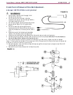
2 Connect the Scrub Deck Lift Actuator (completely
assembled) to the Actuator Power Cord Adapter
56407502
(Figure 10)
(see “Diagnostic and Service
Tools”).
3 Connect the red alligator clip to the positive battery
terminal.
4 Connect the black alligator clip to the negative battery
terminal.
5
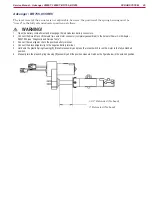
See Figure 11.
Hold onto the metal nut
(A)
and press
the rocker switch to run the motor and retract the nut
towards the motor housing (the IN or Retract Limit).
6 With the motor laying on a flat surface, place a 3/8”
pin or bolt
through the top mounting holes
(C)
and the
bottom (nut) mounting holes
(D)
because you will be measuring the distance between them..
7 Manually turn the metal nut
(A)
until the distance between the outer edge of one pin and the inner edge of the other pin*
matches the Retracted setting shown below.
8 Hold the metal nut and press the rocker switch, running the motor until it stops. If the measurement doesn’t match 13.25” (33.65cm)
as shown below, pry off the black cover
(B)
to access the Cam Adjuster.
9 Using a 1/2” socket, gently turn the adjuster CW to increase travel, CCW to decrease travel of the Drive Nut. Each click of the adjuster
will change the nut travel by 0.09” (2.29mm) or just under 3/32”.
10 After each adjustment, re-check the travel by holding the metal nut and running the actuator IN and OUT, checking against the values
below.
11 Repeat until it is set correctly and replace the Cam Adjuster cover
(B)
.
12 DO NOT TURN THE NUT before mounting - mark the position on the shaft if helpful.
Actuator Setting – mounting hole center to center:
Retracted: 9.00” +/- .06
Extended: 13.25” +/- .06
* It’s not practical to measure center to center of the holes, so an outer edge to inner edge of the pins measurement is suggested.
FIGURE 11
FIGURE 10


