background image


Chapter 5

  Assembling 

95


  Directly placing the polarizer 

When the LED diascopic illumination base is in use,
the polarizer can be removed from the polarizer 
attachment and can be individually attached to the 
diascopic illumination base. Fit it under the stage 
plate of the diascopic illumination base. The stage 
plate can be used as is. 


3


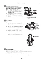
Attach the P-SXY64 XY Stage. 


Attach the P-SXY64 XY Stage to the P2-PB Plain Base, 
P2-DBL LED Diascopic Illumination Base or P2-DBF Fiber
Diascopic Illumination Base. 

(1)  Remove the fastener for the stage. Loosen the four 

M4 hexagon socket head bolts for the stage using a 
hex wrench (nominal designation: 3). 

(2)  Loosen the M4 set screw for the stage plate on the 

base using a hex driver (nominal designation: 2) to 
detach the stage plate. 

(3)  Attach the P-SXY64 Stage using the four tap holes 

that are located under the stage plate attachment 
position. 
Move the upper plate of the P-SXY64 to align the 
installation holes on the lower plate with the tap 
holes, insert the four M6 hexagon socket head bolts 
and firmly tighten them using a hex wrench (nominal 
designation: 5). 

(4)  Fit the glass plate supplied with the P-SXY64 XY 

Stage on to the upper plate of the stage. The glass 
plate has chamfered corners including one small 
chamfered corner. Align the small chamfered corner 
with the right rear side of the stage (as viewed from 
the front) to fit the glass plate on the stage, and 
tighten the glass plate fixing screw. 


Attaching the P-SXY64 Stage   

by tightening the bolts 


Y-stroke limit bolt 

When attaching the P-SXY64 to the P-PS32 Plain Stand, 
screw the Y-stroke limit bolt supplied with the P-SXY64 
into the stage. Use a hex wrench (nominal designation: 
2.5) when tightening the M3 hexagon socket head bolt. 


Small 
chamfered 
corner 

Glass plate 
fixing screw

Stage fixing 
bolts (x4) 

Y-stroke limit bolt 

Fastener 

Fastening 
bolts (x4) 

Summary of Contents for SMZ18

Page 1: ... M608EN01 Research Stereo Microscope SMZ25 SMZ18 Instruction Manual M608 E 13 5 NF 1 ...

Page 2: ......

Page 3: ...ithout notice The equipment described in this manual may differ from the actual product in its appearance Although every effort has been made to ensure the accuracy of this manual errors or inconsistencies may remain If you note any points that are unclear or incorrect please contact your nearest Nikon representative Some of the equipment described in this manual may not be included in the set you...

Page 4: ... and Operations of the Devices Chapter 5 Assembling lists the components of this microscopy system considering that the system allows various combination Devices needed for each illumination method can be identified Symbols Used in This Manual The following symbols are used in this manual Symbols for Safety WARNING CAUTION Highlights important information that should be noted for safety Read Safet...

Page 5: ...ation Flowchart 8 2 Procedure for Microscopy under Episcopic Illumination 9 3 Procedure for Microscopy under Diascopic Illumination 13 4 Procedure for Epi fluorescence Microscopy 16 Specific Operations 19 1 Turning On the Power 20 2 Adjusting the Brightness 21 3 Switching the Optical Path of the Tube 22 4 Adjusting the Angle of Depression 23 5 Adjusting the Diopter 23 6 Adjusting the Interpupillar...

Page 6: ...XY Stage 50 5 6 C SSL DIA Sliding Stage 50 5 7 C TRS Tilting Stage 50 6 Tubes 51 6 1 P2 TERG 100 P2 TERG 50 Trinocular Tilting Tube 51 6 2 P2 TL100 Trinocular Tube L 51 7 Episcopic Illuminator 52 7 1 P2 CI Coaxial Epi Illuminator 52 7 2 C FDF Flexible Double Arm Fiber Illumination Unit 53 7 3 P2 FIR Ring Fiber Illumination Unit 53 7 4 P2 FIRL LED Ring Illumination Unit 53 8 Diascopic Illuminator 5...

Page 7: ... Other Devices Optional 94 Troubleshooting 97 1 Image Viewing 98 2 Operation 98 3 Motorized Devices 99 Maintenance and Storage 101 1 Cleaning 102 1 1 Cleaning Lenses 102 1 2 Cleaning Parts Other than the Lens 102 1 3 Disinfecting the Product 103 2 Storage 103 3 Periodic Inspection Charged 103 Specifications 105 1 Microscopy Principles 106 2 Performance Properties 106 3 Physical Properties 110 ...

Page 8: ...ked with this symbol may lead to serious injury or death CAUTION Disregarding instructions marked with this symbol may lead to injury or property damage Label Attached to the Product The label attached to the products shown below indicates that attention should be paid to use of these products Before using a product with the label attached be sure to carefully read the manual Light safety label IE...

Page 9: ...be several minutes after finishing the diascopic observation Label Position Light leakage warning label Caution Light leakage Do not use the epi fluorescence attachment while the filter cube replacement cover is open Harmful light including ultraviolet light may leak and affect fluorescence observation Label Position PHOTO 2 1 P2 EFLM Motorized Epi Fluorescence P2 EFLI Epi Fluorescence Attachment ...

Page 10: ...he device matches the power supply to be used If the input rating does not match do not use the power supply and contact your local representative Using the device with the power supply can cause the device to be damaged 4 Notes on the power cord Be sure to use the specified power cord Use of other power cords may result in malfunction or fire This product is classified as having Class I protectio...

Page 11: ...ssure gas The lamps contain sealed gas under very high pressure And the pressure increases when the lamp is on Crack or dirt of the lamp tube strong external force or impact or use beyond the tube s life may cause the encapsulated gas to leak or the lamp to blow up If this happens an accident such as gas inhalation or injury with glass may take place Heat When the lamp is lit the lamp and surround...

Page 12: ...vements of motorized device with remote controls or personal computers Before operation check the state of the entire microscope system to ensure safety when operating the motorized devices If having touched the zooming body focus knob objective stage or devices or samples placed on the stage your hand or fingers may be caught and injured Before starting to operate keep your hands away from these ...

Page 13: ...hour Take at least 10 to 15 minute breaks between observation sessions Adjust the layout of other equipment used and the height of your chair 13 Cautions on use transportation and storage This product must be operated transported or stored in accordance with the following conditions If you install the product at a location with high temperature and high humidity mold and or condensation may be gen...

Page 14: ... product near water Make sure the ambient temperature is 0 to 40 C and humidity is 60 or less When transporting or storing this product the ambient temperature must be 20 to 60 C with the humidity at 90 RH max with no condensation If you install the product at a location with high temperature and high humidity mold and or condensation may be generated on the lenses Furthermore performance deterior...

Page 15: ...scopic illuminators This chapter introduces the names of the devices and operation sections with the following three types of system configuration as examples 1 Microscopy system under episcopic illumination with an SMZ18 Zooming Body 2 Microscopy system under diascopic illumination and epi fluorescence illumination with an SMZ25 Zooming Body 3 Compact system with an SMZ18 Zooming Body For details...

Page 16: ... focus knob To P2 CTLB Control Box Zooming knob Optical path switching lever P2 CTLB Control Box P2 RNI2 Intelligent Nosepiece SMZ18 Zooming Body P2 RLY Relay Box P2 CI Coaxial Epi Illuminator P2 FU Focus Unit DS camera head P2 TERG 100 Trinocular Tilting Tube Fine focus knob Coarse focus knob Focus knob torque adjustment ring Eyepiece Diopter adjustment ring Fiber to C FLED2 LED Light Source for ...

Page 17: ...2 CTLA Control Box SMZ25 Zooming Body P2 RNI2 Intelligent Nosepiece P2 EFLM Motorized Epi Fluorescence Attachment P2 MFU Motorized Focus Unit DS camera head P2 TERG 100 Trinocular Tilting Tube Eyepiece Diopter adjustment ring STOP switch Turret address check window Light shielding plate LED power source ON OFF switch LED brightness control dial HG fiber to the HG precentered fiber illuminator Powe...

Page 18: ... in Chapter 4 10 1 P2 RC Remote Controller 1 LCD 6 Filter cube switching button 7 LCD display switching button 5 Focus speed indicator 13 Escape button 14 Escape ON OFF indicator 17 ALZ button 18 ALZ ON OFF indicator 19 Diascopic LED brightness control button 9 Capture button 2 Backlight control dial 4 Fine coarse focus switching button 8 Z reset button 3 Focus knob 12 Zoom step indicator 10 Zoom ...

Page 19: ...nectors see Chapter 5 3 Assembly Procedures Optical path switching lever Fine focus knob Coarse focus knob Focus knob torque adjustment ring Zooming knob Clamp tool Coarse focus knob P PS32 Plain Stand Fine focus knob Objective Zooming knob SMZ18 Zooming Body P2 FMDN Focus Mount DS camera head P2 TL100 Trinocular Tube L Stage plate Eyepiece Diopter adjustment ring Aperture diaphragm dial ...

Page 20: ...Chapter 1 Components 6 ...

Page 21: ...ure 2 Procedure for microscopy under diascopic illumination Procedure 3 Procedure for epi fluorescence microscopy It is assumed that all required components are attached to the microscope with all necessary cables properly connected If assembly of the microscopy system has not yet been completed complete assembly as described in Chapter 5 3 Assembly Procedures When using the motorized system or in...

Page 22: ...in the sample with microscopy under diascopic illumination follow the procedure below In microscopy under diascopic illumination using an epi fluorescence attachment attach an empty cube supplied with the microscope to the epi fluorescence attachment and bring it into the optical path In a compact system of an SMZ18 Zooming Body combined with a P PS32 Plain Stand and P2 FMDN Focus Mount perform th...

Page 23: ...and immediately under the objective Setting the sample 3 Bring an objective into the optical path Turn the nosepiece to bring the objective to be used into the optical path Check that the objective falls into the click position when turning the nosepiece See Chapter 3 8 2 Switching Objectives Rotating the nosepiece P2 CI Coaxial Epi Illuminator The P2 CI Coaxial Epi Illuminator is supplied with a ...

Page 24: ... switching lever 100 to the vertical tube The division ratio of the light amount differs depending on the tube types See Chapter 3 3 Switching the Optical Path of the Tube 6 Adjust the depression angle of the tilting tube When using the P2 TERG 100 or P2 TERG 50 Trinocular Tilting Tube change and adjust the angle of the binocular part to facilitate microscopy The low eye level P2 TL100 Trinocular ...

Page 25: ...ng on the Sample Focusing 10 Change the magnification using the zooming knobs Turn the zooming knobs on the right and left of the SMZ18 Zooming Body to change the magnification The figure shows the turning directions of a knob and the corresponding changes in magnification Turning the knob backward Magnification increase Turning the knob forward Magnification decrease The magnification continuousl...

Page 26: ...r completing microscopy Turn off the P2 CTLB Control Box by pressing the power switch to the O position Check that the power LED on the control box turns off Also turn off the LED light source for fiber illuminator Power off Power LED Off Power switch O position ...

Page 27: ...nt to the position when power was turned on Other motorized devices also perform internal initialization Power supply to the P2 DBL LED Diascopic Illumination Base For a system configuration where a control box has been connected the control box supplies power to the P2 DBL LED Diascopic Illumination Base The P2 DBL therefore need not be connected to a power supply See Chapter 4 8 1 P2 DBL LED Dia...

Page 28: ...PLAY DISPLAY BRIGHTNESS BRIGHTNESS ESCAPE ESCAPE ALZ ALZ LIMIT LIMIT ZOOM ZOOM STEP STEP Z RESET Z RESET Z SPEED Z SPEED ZOOM STEP ZOOM STEP Coarse Coarse FL Cube FL Cube ON OFF ON OFF ON OFF ON OFF ON OFF ON OFF ON OFF ON OFF Fine Fine Ex Fine Ex Fine 1x 1x 0 5x 0 5x 0 1x 0 1x Remote on brightness control Aperture diaphragm The SMZ25 Zooming Body is equipped with an aperture diaphragm Turn the ap...

Page 29: ...1 mm second 10 Change the magnification by zooming in and out Press the zoom buttons on the remote controller to change the magnification of the zooming body Upper zoom button Magnification increase Lower zoom button Magnification decrease The magnification changes in the range from 0 63x to 15 75x Pressing and holding the buttons causes the magnification to change continuously 1 2 3 4 DISPLAY DIS...

Page 30: ... the optical path Press the filter cube switching buttons FL1 to FL4 on the remote controller to bring the desired filter cube into the optical path FL1 to FL4 designate the turret addresses of the epi fluorescence attachment The LED of the pressed button lights so that the turret address on the optical path can be identified The address on the optical path can be identified also through the turre...

Page 31: ...ghtness Refer to the instruction manual for the fiber light source 15 Adjust the focus Step 9 in 3 Procedure for Microscopy Under Diascopic Illumination 16 Change the magnification by zooming in and out Step 10 in 3 Procedure for Microscopy Under Diascopic Illumination 17 Turn off the power after completing microscopy Turn off the HG precentered fiber illuminator and P2 CTLA Control Box by pressin...

Page 32: ...Chapter 2 Microscopy Procedures 18 ...

Page 33: ...19 Chapter 3 Specific Operations This chapter describes how to work with this microscope system in order to observe samples For details about using the individual devices see Chapter 4 ...

Page 34: ...nit See the instruction manual for the P2 FIRL LED Ring Illumination Unit P DF LED Dark Field Unit See the instruction manual for the P DF LED Dark Field Unit When using an illuminator whose light source is an HG precentered fiber illuminator or fiber illumination LED light source also turn on the power to the light source See the instruction manual for the light source When using multiple power s...

Page 35: ...D Light source for fiber illuminator See the instruction manual supplied with the C FLED2 for details P2 CI Coaxial Epi Illuminator C FDF Flexible Double Arm Fiber Illumination Unit P2 FIR Ring Fiber Illumination Unit P2 DBF Fiber Diascopic Illumination Base Adjust the brightness using the C HGFI C HGFIE HG Precentered Fiber Illuminator See the instruction manual supplied with the C HGFI C HGFIE f...

Page 36: ... pushed in or pulled out Do not leave the lever stopped partway Switching the optical path Distribution of Light with Optical Path Switching Tube Lever position Binocular part Vertical tube Left Right P2 TERG 100 Trinocular Tilting Tube Pulled out 100 100 0 Pushed in 100 0 100 P2 TERG 50 Trinocular Tilting Tube Pulled out 100 100 0 Pushed in 100 50 50 P2 TL100 Trinocular Tube L Pulled out 100 100 ...

Page 37: ...ustment rings of the right and left eyepieces to 0 1 2 3 4 DISPLAY DISPLAY BRIGHTNESS BRIGHTNESS ESCAPE ESCAPE ALZ ALZ LIMIT LIMIT ZOOM ZOOM STEP STEP Z RESET Z RESET Z SPEED Z SPEED ZOOM STEP ZOOM STEP Coarse Coarse FL Cube FL Cube ON OFF ON OFF ON OFF ON OFF ON OFF ON OFF ON OFF ON OFF Fine Fine Ex Fine Ex Fine 1x 1x 0 5x 0 5x 0 1x 0 1x Remote controller Foot switch Adjusting the diopter 2 Maxim...

Page 38: ...Adjust to match the distance between your right and left eyes This adjustment is required for each user Look into both eyepieces and move the binocular part of the tube so that the right and left fields of view merge into a single circle Adjusting the interpupillary distance ...

Page 39: ...ovement See Chapter 4 10 2 AZ FSW Foot Switch 1 2 3 4 DISPLAY DISPLAY BRIGHTNESS BRIGHTNESS ESCAPE ESCAPE ALZ ALZ LIMIT LIMIT ZOOM ZOOM STEP STEP Z RESET Z RESET Z SPEED Z SPEED ZOOM STEP ZOOM STEP Coarse Coarse FL Cube FL Cube ON OFF ON OFF ON OFF ON OFF ON OFF ON OFF ON OFF ON OFF Fine Fine Ex Fine Ex Fine 1x 1x 0 5x 0 5x 0 1x 0 1x Focus operation Notes on turning the focus knobs When using the ...

Page 40: ...cus unit Be sure to adjust the torque to an appropriate level Note that turning the fine control knob will cause the coarse control knob to also turn changing the torque of the fine control knob 2 1x SHR WD 60 Plan Apo Adjusting the torque of the focus knobs Focusing stroke P2 FU Focus Unit Focusing stroke 100 mm Stroke per rotation of the focus knobs Coarse control 18 50 mm per rotation Fine cont...

Page 41: ... Magnification increase Front side pedal Magnification decrease See Chapter 4 10 2 AZ FSW Foot Switch 1 2 3 4 DISPLAY DISPLAY BRIGHTNESS BRIGHTNESS ESCAPE ESCAPE ALZ ALZ LIMIT LIMIT ZOOM ZOOM STEP STEP Z RESET Z RESET Z SPEED Z SPEED ZOOM STEP ZOOM STEP Coarse Coarse FL Cube FL Cube ON OFF ON OFF ON OFF ON OFF ON OFF ON OFF ON OFF ON OFF Fine Fine Ex Fine Ex Fine 1x 1x 0 5x 0 5x 0 1x 0 1x Image Zo...

Page 42: ...e falls into the click position when turning the nosepiece Stereoscopic view and vertical view An intelligent nosepiece has two click positions for each objective The click position switches between stereoscopic view and vertical view Microscopy with vertical view is possible when needed for example when taking a picture The click position of the objective can be checked by the position of the obj...

Page 43: ...t to be observed XY stroke of the stage with the X Y shift knob and stroke per rotation of the knob X 150 mm 37 5 mm per rotation Y 100 mm 24 1 mm per rotation Usage restriction If the P SXY64 XY Stage is mounted on the P PS32 Plain Stand the movement of the stroke in the Y direction is restricted Also see Chapter 4 5 5 P SXY64 XY Stage Shift using the P SXY64 XY Stage 9 2 Using the Sliding Stage ...

Page 44: ... to a sample through an objective or directly so that an image resulting from the light reflected from the sample is observed Episcopic illumination is used for observing samples which do not transmit light such as metal and mineral sections In addition if the P2 CI Coaxial Epi Illuminator is attached illumination along the optical axis for observation can also be emitted which is effective for ob...

Page 45: ... observation of samples that are difficult to be observed under ordinary bright field diascopic illumination such as transparent materials and crystals and tissues and minute organisms in culture solutions See Chapter 4 8 Diascopic Illuminator and select the appropriate device based on the objective of microscopy P2 DBL LED Diascopic Illumination Base P2 DBF Fiber Diascopic Illumination Base P DF ...

Page 46: ...g because of its characteristics Make sure you are familiar with and observe all warnings and cautions described at the beginning of this instruction manual 13 1 Switching Filter Cubes The turret of the epi fluorescence attachment is rotated to switch the four filter cubes attached to the turret Turret rotation operation P2 EFLI Epi Fluorescence Attachment Filter cube switching knob of the device ...

Page 47: ... switching to epi fluorescence rather than emitting strong excitation light to the sample from the beginning When doing so follow the operational tips below Start with low magnification under bright field diascopic illumination If the sample is not transparent use the P2 EFLBF Filter Cube Bright Field to obtain the entire image by reflected light Gradually increase the magnification When the targe...

Page 48: ...izontally loosen the attachment guide fixing screw and adjust the orientation of the camera After making the appropriate adjustments tighten the screw Adjusting the camera orientation 3 Select the camera scene mode suitable for the microscopy type 4 Adjust the camera s white balance When using diascopic illumination first capture an image of the top surface of the stage glass When using episcopic ...

Page 49: ...icrography of the color fading portion requires a prolonged exposure time resulting in poor color reproduction and low quality images Move the sample so that the image of the portion that has not been exposed to excitation light can be captured To obtain the best results use the diascopic illumination method to select a specimen section for photomicrography and then switch to the fluorescent metho...

Page 50: ... see the instruction manual supplied with the corresponding product P2 CTLA Control Box Items Default Tools Objective NIS Elements and setup tools DS L3 Eyepiece Setup tools DS L3 Epi fl filter cube NIS Elements and setup tools DS L3 Motorized focus unit lower limit 0 mm NIS Elements remote controller Motorized focus unit escape distance 20 mm NIS Elements and setup tools ALZ function OFF NIS Elem...

Page 51: ...37 Chapter 4 Functions and Operations of the Devices This chapter describes the main functions and how to use the devices ...

Page 52: ...of the zooming body Turning the knob backward Magnification increase Turning the knob forward Magnification decrease Turning the knob causes the magnification to continuously change in the range from 0 75x to 13 5x 18 1 zoom ratio Magnification values are marked on the zooming knobs Click stop of the zooming knobs operates at the positions of 0 75x 1x 2x 3x 4x 5x 6x 8x 10x 12x and 13 5x It is also...

Page 53: ...h time the zoom step switching button on the remote controller is pressed the step size changes in the following order 1x 0 5x then 0 1x When a step size is selected the corresponding step LED indicator lights The right pedals of the foot switch can also be used to zoom in and out images as well as the zoom buttons on the remote controller Right rear pedal Magnification increase Right front pedal ...

Page 54: ...n of 50x switch the objective as follows 1 2 3 4 DISPLAY DISPLAY BRIGHTNESS BRIGHTNESS ESCAPE ESCAPE ALZ ALZ LIMIT LIMIT ZOOM ZOOM STEP STEP Z RESET Z RESET Z SPEED Z SPEED ZOOM STEP ZOOM STEP Coarse Coarse FL Cube FL Cube ON OFF ON OFF ON OFF ON OFF ON OFF ON OFF ON OFF ON OFF Fine Fine Ex Fine Ex Fine 1x 1x 0 5x 0 5x 0 1x 0 1x Use example of the ALZ function ALZ button ALZ ON OFF indicator MAG 5...

Page 55: ...us can be adjusted using the coarse fine focus knobs on the right and left of the focus mount The figure shows the turning directions of the focus knob and the corresponding vertical movements of the focus mount Turning the knob backward Upward movement Turning the knob forward Downward movement Focusing stroke 100 mm Stroke per rotation of the focus knob Coarse control 18 50 mm rotation Fine cont...

Page 56: ... focusing system The focus mount is attached with the SMZ18 or SMZ25 Zooming Body through the P2 RNI2 Intelligent Nosepiece or the P2 FM Focus Mount Adapter The square support is attached with the P2 PB Plain Base P2 DBL LED Diascopic Illumination Base or the P2 DBF Fiber Diascopic Illumination Base Three types of motorized stands can be configured Focusing movement of the motorized focus unit is ...

Page 57: ... switch the speed Each time the button is pressed the focus speed is cyclically switched in the order of coarse fine and extra fine When the focus speed is changed the corresponding indicator Coarse Fine ExFine lights Coarse 2 to 10 mm second Fine 0 2 to 5 mm second Extra fine 0 01 to 0 1 mm second Forced stop of motorized movement The motorized focus unit is equipped with the STOP switch on the l...

Page 58: ... mm The setting value can be changed using the NIS Elements of remote controller Escape setting Pressing the Escape button causes the vertical movement part to move upward by the preset distance so that it stays in position The vertical movement is not possible in this escape status Pressing the Escape button again causes the vertical movement part to return to the previous position Pressing and h...

Page 59: ... the same time Doing so may cause malfunction When the focus knobs reach their rotational limits for the unit s vertical movement do not forcibly turn it further Doing so may cause malfunction 1 x SHR Plan apo WD 60 Do not turn the knobs in the opposite direction Torque of the focus knobs The torque of the coarse control knobs can be changed by turning the torque adjustment ring on the base of the...

Page 60: ...n the intelligent nosepiece For systems where a control box has been connected the objective attachment position addresses and vertical view state are sent to the control box via a motorized focus unit or relay box and then transmitted to the DS L3 DS Camera Control Unit and personal computer P2 RNI2 Intelligent Nosepiece 1 x SHR Plan apo WD 60 2 x SHR Plan apo WD 20 2 x SHR Plan apo WD 20 1 x SHR...

Page 61: ... select 2x magnification or higher If magnification less than 2x is selected shading will occur or part of the field of view will be missing Attach the 1 4 lambda plate supplied with the coaxial epi illuminator to the position from which the protection ring supplied with the 0 5x objective or the correction glass supplied with the 1x objective has been removed Usage restriction When the episcopic ...

Page 62: ... being observed The plain base has three indents for holding the base front of the base s top board and on the right and left rear P2 PB Plain Base Tap holes for attaching accessories The base s top board has tap holes for attaching various accessories Tap holes 2 to 5 are not penetrating to prevent ingress of solution into the base 1 2 M4 Positioned under the stage plate attachment section of the...

Page 63: ...p board has tap holes for attaching various accessories The tap holes are not penetrating to prevent ingress of solution into the base 1 2 M4 Positioned under the stage plate attachment part of the base Used for multiple purposes 2 4 M6 Positioned under the stage plate attachment part of the base Used for attaching the P SXY64 XY Stage 3 2 M4 Positioned at the center on the top surface of the base...

Page 64: ... per rotation Load weight 5 kg or less Applicable range of diascopic illumination bright field OCC 150 x 100 mm travel range Shading may occur in diascopic illumination or OCC illumination in the low zoom magnification range 5 6 C SSL DIA Sliding Stage This stage enables fine movement of a sample when its side is pushed Remove the stage plate of the base and attach it to the upper surface of the s...

Page 65: ...100 The light from the optical path of the right eye is diverged to the vertical tube An image in the right eye s optical path is captured 6 1 P2 TERG 100 P2 TERG 50 Trinocular Tilting Tube This is an ergonomic tube that enables the angle of depression to be adjusted The angle can be continuously changed by moving the binocular part as indicated by the arrow in the figure Adjust the angle to facil...

Page 66: ...e imaging system due to light reflected in the optical system Attach the plate to the tip of the 0 5x or 1x objective Before attaching the plate remove the protection ring from the tip of the 0 5x objective and remove the correction ring from the tip of the 1x objective The brightest illumination is generated when the while circle indicator is at the front Select a position that has the optimum br...

Page 67: ...arms to be freely swung centered around a single axis Z axis This allows the arms to be pushed aside without having to unlock the arm joints After that if the arm position is returned by the rotation of the single axis the arm will stop at the position that was locked first C FIDH Fiber Holder 7 3 P2 FIR Ring Fiber Illumination Unit This illuminator is connected to the C FLED2 LED Light Source for...

Page 68: ...ervation of samples in containers such as petri dishes The base has three indents for holding the base front of the base s top board and on the right and left rear The stage plate can be replaced with a stage having an X Y shift knob or a sliding stage It is also possible to attach other devices such as a fiber illuminator or diascopic polarizing device to expand the base s functions OCC oblique c...

Page 69: ...ng that contains a diffuser plate to control excess contrast for OCC 45 mm dia filter A 45 mm dia filter no thicker than 5 mm can be dropped onto the filter dropping ring attached to the base optical path immediately under the grass plate Tap holes for attaching accessories The base s top board has tap holes for attaching various accessories Tap holes 2 to 5 are not penetrating to prevent ingress ...

Page 70: ... in combination with the selected magnification and phase amount of the sample In addition since the OCC adjustment knob has a scale the position of the knob can be reproduced Condenser lens The base contains condenser lenses for low high magnification microscopy Switch the condenser lens based on the objective being used to ensure uniform diascopic illumination A wide range of observation magnifi...

Page 71: ...imple polarizing device that consists of a polarizer unit and analyzer unit First remove the stage glass from the diascopic illumination base Attach the base plate of the polarizer unit orient the polarizer as required and then set the 90 mm dia stage glass supplied with the device The stage glass can be rotated Attach the analyzer to the tip of the objective and tighten the clamp screw to stabili...

Page 72: ...lacement cover is open Harmful light including ultraviolet light may leak and affect fluorescence observation Immediately after diascopic observation using an epi fluorescence attachment the front face of the empty cube may become hot resulting in burns Do not touch the front face of the empty cube Replace the empty cube several minutes after finishing the diascopic observation Be sure to attach f...

Page 73: ... filter cubes the addresses of the attachment positions are FL1 to FL4 For the attachable filter cube types those for fluorescence bright field and empty are available On the remote control press the filter cube switching buttons FL1 to FL4 to specify the turret address of the filter cube to be placed into the optical path The LED of the pressed button lights so that the turret address on the opti...

Page 74: ...aside to positions up to 45 horizontally to the rear When not in use the plate can be pushed aside to positions up to 170 Bright field episcopic observation This is useful for observing the entire image of the opaque specimen during fluorescence observation Although the P2 EFLBF Filter Cube contains the UV blocking filter adjust the brightness of the illuminator so that illumination is not too bri...

Page 75: ... ON OFF ON OFF ON OFF ON OFF ON OFF ON OFF ON OFF Fine Fine Ex Fine Ex Fine 1x 1x 0 5x 0 5x 0 1x 0 1x Front Right Side P2 RC Remote Controller 1 LCD 6 Filter cube switching button 7 LCD display switching button 5 Focus speed indicator 13 Escape button 14 Escape ON OFF indicator 17 ALZ button 18 ALZ ON OFF indicator 19 Diascopic LED brightness control button 9 Capture button 2 Backlight control dia...

Page 76: ...ification to decrease Pressing and holding the button causes the magnification to change continuously 11 Zoom step switching button Switches the zoom step size in order of 1x 0 5x and 0 1x 12 Zoom step indicator When the zoom step size is changed the corresponding LED 1x 0 5x and 0 1x lights 13 Escape button Moves the vertical movement part upward by the preset distance so that it stays in positio...

Page 77: ...P B 7 Field of view Stereoscopic view or Vertical view 1 7 2 3 4 5 6 10 2 AZ FSW Foot Switch The AZ FSW Foot Switch is a controller that enables a pedal to be used for focus and zoom operations The foot switch is connected to the FOOT connector of the P2 CTLA Control Box To use the foot switch the P2 RC Remote Controller must be connected to the P2 CTLA Control Box PHOTO CTRL AZ FSW Foot Switch 4 ...

Page 78: ... 0 75 to 4 0 4 1 to 8 0 8 1 to 13 5 Nosepiece address 1 5 mm second 4 mm second 2 mm second 2 2 mm second 1 mm second 0 5 mm second Extra fine Magnification SMZ25 0 63 to 5 0 5 1 to 10 0 10 1 to 15 75 SMZ18 0 75 to 4 0 4 1 to 8 0 8 1 to 13 5 Nosepiece address 1 0 5 mm second 0 4 mm second 0 2 mm second 2 0 2 mm second 0 1 mm second 0 0 5 mm second 2 Right foot pedal Right rear of the foot pedal mo...

Page 79: ...the AZ FSW Foot Switch For operations using a DS camera control unit such as the DS L3 after a DS camera head has been attached to the microscope connect the DS camera control unit to the P2 CTLA Control Box USB connection Next connect the photo release to the AZ FSW Foot Switch connected to the control box The camera can then capture images simply by stepping on the pedal of the photo release AZ ...

Page 80: ...HG Precentered Fiber Illuminator Switches the ND filter and opens closes the shutter 7 C HGFIE HG Precentered Fiber Illuminator Communications 8 1 DS L3 DS Camera Control Unit plus DS camera Communications 8 2 Personal computer plus DS U3 DS Camera Control Unit plus DS camera Communications 9 AC adapter 24 V power input The power supply for control provides power for the board in the control box a...

Page 81: ...cable connected to the AC adapter use the one specified in Chapter 8 2 Performance Properties USB Connect to the USB port of a personal computer or the DS L3 LEDDIA Connect to the LED light control terminal of the P2 DBL LED Diascopic Illumination Base RELAY Connect to the P2 RLY Relay Box or P2 RLYC Relay Cable DC24V IN Connect to the 24 V AC adapter HGFIE Connect to the RS232C port of the C HGFI...

Page 82: ...he P2 MFU Motorized Focus Unit vertically and adjust the magnification of the SMZ25 Zooming Body 11 AZ PCR Photo Release Detects the switch states and captures images 12 C HGFIE HG Precentered Fiber Illuminator Switches the ND filter and opens closes the shutter 13 C HGFIE HG Precentered Fiber Illuminator Communications 14 1 DS L3 DS Camera Control Unit plus DS camera Communications 14 2 Personal ...

Page 83: ...been connected the P2 RLYC Relay Cable is used to connect the SMZ18 Zooming Body to the RELAY connector of the P2 CTLB Control Box This enables the status detection signals to be relayed P2 RLYC Relay Cable View A USB Connect to the USB port of a personal computer or the DS L3 LEDDIA Connect to the LED light control terminal of the P2 DBL LED Diascopic Illumination Base using the cable supplied wi...

Page 84: ...Chapter 4 Functions and Operations of the Devices 70 ...

Page 85: ...work with at least two people Put hands in the depression at the front of the base and the rear of both sides to lift up the system Be very careful not to let fingers be caught when putting it down Tools necessary for assembly Tools Devices that supply tools Hex wrench nominal designation 2 5 Intelligent nosepiece P SXY64 XY Stage Hex wrench nominal designation 3 P SXY64 XY Stage Hex wrench nomina...

Page 86: ...motorized focus unit Connectors NP ZOOM and FL P2 CTLA control box P PS32 plain stand Eyepiece Eyepiece tube TV tube adapter DS camera head C mount adapter Filter cube P2 EFLBF is equipped with 1 4 lambda plate for 0 5x and 1x objectives HG fiber C HGFI C HGFIE HG precentered fiber illuminator Epi fluorescense attachment With light shielding plate Objective 1 4 lambda plate P2 FU focus unit SMZ18 ...

Page 87: ...lyzer unit Attached to 0 5x or 1x objective Polarizer unit Attached to base or stand C FIDH fiber holder Other Stages Attached to base or stand Stage adapters for AZ P SXY64 XY stage C SSL DIA sliding stage C TRS tilting stage P2 POL simple polarizing attachment C FLED2 LED light source for fiber illuminator Other Devices P DF LED dark field unit Optional P DF LSP light shielding plate is availabl...

Page 88: ...nt glass stage plate P PS32 Plain Stand With an acrylic stage plate P SXY64 XY Stage Optional Optional Optional C SSL DIA Sliding Stage Tube P2 TERG 100 Trinocular Tilting Tube P2 TERG 50 Trinocular Tilting Tube P2 TL100 Trinocular Tube L Eyepiece C W 10XB Eyepiece C W 15X Eyepiece C W 20X Eyepiece C W 30X Eyepiece Episcopic Illuminator P2 CI Coaxial Epi Illuminator Optional With a 1 4 lambda plat...

Page 89: ...case When configuring the DIA EPI FL System select the dia illumination base The following figure shows an example of attaching the P2 DBL LED Diascopic Illumination Base to the P2 FU Focus Unit CAUTION Heavy Object The base and focus unit are heavy The focus unit is especially heavy so be very careful not to drop it when unpacking or installing Working with two or more people is recommended P2 FU...

Page 90: ...he bottom of the base and tighten firmly using a hex wrench nominal designation 6 Attaching the base by tightening the bolts 4 Install the attached device on the desk Installing the base Attaching the stage plate Attach the stage plate Depending on the type of the base either a transparent glass stage plate or an acrylic stage plate is supplied The acrylic plate is black on one side and milky whit...

Page 91: ...urce for Fiber Illuminator See the instruction manual for the light source for details Attaching the fiber by tightening the screw Connecting a cable to the P2 DBL LED Diascopic Illumination Base Connect the cable to the connector on the left Connect the LED brightness control terminal CTRL with the connector LEDDIA on the control box using the CTRL cable supplied with the control box Connect the ...

Page 92: ...d bolts 2 Drop and fit the dovetail groove on the rear side of the intelligent nosepiece onto the dovetail of the focus unit mount from the top Attaching the intelligent nosepiece 3 Firmly tighten the two fixing bolts using a hex driver nominal designation 4 After tightening the bolts put the rubber caps back onto the bolt holes Firmly tightening the bolts 4 The cover on the left side as viewed fr...

Page 93: ...ent nosepiece When attaching to the focus mount adapter Step 1 is not necessary when attaching the zooming body to the focus mount adapter Proceed to Step 2 1 Detach the objective attachment adapter dovetail and ring attached under the zooming body Loosen the three M3 hexagon socket head bolts using a hex wrench nominal designation 2 5 1 0 7 5 Detaching the objective attachment adapter 2 Completel...

Page 94: ... signal cables Connect the cables necessary to detect the device state or to drive the motorized devices 1 Connect the signal cables The relay box has connectors NP ZOOM and FL on the left side as viewed from the front The P2 MFU Motorized Focus Unit has connectors NP ZOOM and FL on the left side of the unit mount as viewed from the front The following cables are connected to each connector NP Con...

Page 95: ...IN JAPAN Cable connection to the motorized focus unit 2 Attach the left cover of the intelligent nosepiece Route the cable and replace the intelligent nosepiece left side cover removed in Step 2 4 Align and fit the two protrusions on the left side cover to the two notches in the top center of the intelligent nosepiece insert the two M5 hexagon socket head fixing bolts in the fixing bolt holes at t...

Page 96: ...on 4 Attaching the relay box P2 FU MA DE IN CHI NA MA DE IN CHI NA SMZ18 MADE IN JAPAN 0 75 1 2 ZOOM FL NP Tightening the bolts for the relay box Connecting the relay cable when not using a relay box Use the P2 RLYC Relay Cable to output the zoom magnification information of the SMZ18 to the P2 CTLB Control Box without using a relay box Connect the relay cable to the round connector on the left si...

Page 97: ...t holes on the rear side of the coaxial epi illuminator using a hex driver nominal designation 2 Insert the fiber to the attachment hole until it reaches the limit and tighten the fixing screw Firmly insert the other end of the fiber into the fiber attachment hole of the C FLED2 LED Light Source for Fiber Illuminator See the instruction manual for the light source for details Attaching the LED fib...

Page 98: ...ables Connect the signal cable that comes from the bottom of the epi fluorescence attachment to the connector FL on the motorized focus unit or relay box In case of the motorized unit connect it inside the left cover of the intelligent nosepiece See 4 Connect the signal cables Attaching the HG fiber Loosen the M4 set screw for the HG fiber on the top of the HG fiber attachment hole on the rear sid...

Page 99: ...e Be sure to attach four cubes to the turret Attach an empty cube to the position to which no filter cube is attached 3 Affix the filter cube indication label Labels indicating the type of filter cube are supplied with the epi fluorescence attachment It is useful to identify the type with the labels Affix a label indicating the type of attached filter cube to the label attachment position at the t...

Page 100: ...ng a hex driver nominal designation 2 Attaching the shielding plate by tightening the screw Attaching to the intelligent nosepiece 1 Separate the ring attached to the light shielding plate The ring is attached to the light shielding plate with the two M2 5 hexagon socket head bolts Remove them using a hex driver nominal designation 2 Removing the ring from the light shielding plate 2 Align the scr...

Page 101: ...be to the round dovetail of the illuminator and tighten the fixing screw P2 TERG1 00 MADE IN CHINA Attaching the tube 9 Attach the eyepiece Attach the eyepiece to the tube Two eyepieces with the same magnification are used Firmly insert the eyepiece until it contacts the end of the tube sleeve BINO PHOTO Attaching the eyepiece Caution when attaching the eyepiece Pay attention when inserting a 10x ...

Page 102: ...In addition scratches or fingerprints on the lens at the end will degrade the microscope images Handle the objective carefully 1 Completely loosen the M4 set screw for the objective at the top front of the zooming body using a hex driver nominal designation 2 2 Align and fit the mark white dot on top of the objective to the objective fixing screw position and rotate the objective counterclockwise ...

Page 103: ...ol Box The figure below shows the connectors on the rear side of the control box and the connection destinations Rear of the P2 CTLA Use a power cord specified in Chapter 8 2 Performance Properties to connect to the 24 V AC adapter USB Connect to the USB port of a personal computer or the DS L3 LEDDIA Connect to the LED light control terminal of the P2 DBL LED Diascopic Illumination Base using the...

Page 104: ...ntrol Box 1 1 2 3 4 DISPLAY DISPLAY BR IG HT NE SS BR IG HT NE SS ESC APE ESC APE ALZ ALZ LIMIT LIMIT ZOO M ZOO M STE P STE P Z RESE T Z RESE T Z SPEE D Z SPEE D ZOO M STE P ZOO M STE P Coarse Coarse FL Cube FL Cube ON O FF ON O FF ON O FF ON O FF ON O FF ON O FF ON O FF ON O FF Fine Fine Ex Fine Ex Fine 1x 1x 0 5x 0 5x 0 1x 0 1x Connecting the control box 2 Connect the AZ FSW Foot Switch optional...

Page 105: ...e top of the support MA DE IN CH INA Attaching the support by tightening the screw Attaching the stage plate An acrylic stage plate having black and milky white planes is supplied with the P PS32 Plain Stand Attach the stage plate with the appropriate side facing up based on the sample to be viewed Loosen the M4 set screw for the stage plate in the front center of the base using a hex driver nomin...

Page 106: ...s for the zooming body on the right side of the zooming body as viewed from the front using a hex driver nominal designation 4 2 Drop and fit the dovetail groove of the zooming body onto the dovetail of the focus mount from the top 3 Remove the two rubber caps for the fixing bolt holes on the right side of the focus mount as viewed from the front Insert the hex driver nominal designation 4 into a ...

Page 107: ...nce attachment See 3 1 Step 8 Attach the tube Attaching the tube by tightening the screw 5 Attach the eyepiece Attach the eyepiece to the tube For details see 3 1 Step 9 Attach the eyepiece 6 Attach the objective Attach the objective to the zooming body The procedure for attaching removing the objective to from the zooming body is the same as for attaching removing it to from the intelligent nosep...

Page 108: ...arm fiber by tightening the screws 2 Attach the P2 POL Simple Polarizing Attachment Attach it to the P2 DBL LED Diascopic Illumination Base or P2 DBF Fiber Diascopic Illumination Base Attach a P2 SHR Plan Apo 0 5X or 1X objective 1 Loosen the M4 set screw for the stage plate on the diascopic illumination base using a hex driver nominal designation 2 to detach the stage plate and fit the base plate...

Page 109: ...t are located under the stage plate attachment position Move the upper plate of the P SXY64 to align the installation holes on the lower plate with the tap holes insert the four M6 hexagon socket head bolts and firmly tighten them using a hex wrench nominal designation 5 4 Fit the glass plate supplied with the P SXY64 XY Stage on to the upper plate of the stage The glass plate has chamfered corner...

Page 110: ...ed on the mount on the tube side attach the TV tube adapter determine the DS camera head orientation and then tighten the TV tube adapter fixing screw 3 Connect the camera cable connector of the DS camera head to the connector CAMERA of the DS L3 DS U3 DS camera control unit using a dedicated camera cable Attaching the camera by tightening the screws Use two camera cable clips that are located on ...

Page 111: ...perly If any of the problems described in this chapter occur be sure to check the table for possible causes before requesting service If you detect problems that are not listed in the table or the problem still persists even after the indicated measures are taken turn off the device and contact your nearest Nikon representative ...

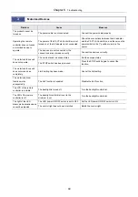
Page 112: ... sample is tilted relative to the stage surface Correctly reposition the sample on the stage 2 Operation Problem Cause Measure Even when looking with both eyes an image does not appear as a single image The interpupillary distance has not been adjusted Adjust the interpupillary distance The diopter has not been adjusted Adjust the diopter distance Eyes become fatigued The interpupillary distance h...

Page 113: ...s not operate The unit is placed in escape status Exit the escape status The STOP switch has been pressed Press the STOP switch again to cancel the function The motorized focus unit does not move down completely Limit setting has been made Cancel the limit setting The motorized zoom function works unexpectedly The ALZ function is enabled Disable the ALZ function The LCD of the remote controller is...

Page 114: ...Chapter 6 Troubleshooting 100 ...

Page 115: ...101 Chapter 7 Maintenance and Storage This chapter describes how to maintain and store the product ...

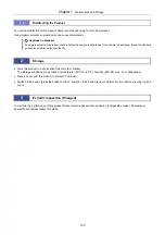
Page 116: ... of the printed characters 1 1 Cleaning Lenses Keep the lens free of dust and fingerprints Any contamination on the lenses or filters will lower the image quality If the lenses have become dirty clean them as follows Cleaning light dirt dust 1 Use an air blower to blow off any dust 2 If any dust remains brush the dust off using a soft brush or gently wipe the dust off using a piece of gauze Cleani...

Page 117: ...stablished for your facility 2 Storage Store this product in a dry location free of mold or mildew The storage conditions are as follows temperature 20 C to 60 C humidity 90 RH max no condensation Place a cover over this product to protect it from dust Switch off the device press the switch to the O position If the device is warm wait for it to cool before covering it with a cover 3 Periodic Inspe...

Page 118: ...Chapter 7 Maintenance and Storage 104 ...

Page 119: ...105 Chapter 8 Specifications ...

Page 120: ...Magnification 0 75 to 13 5x 0 63 to 15 75x NA 0 15 For 1x objective and 13 5x zoom 0 156 For 1x objective and 15 75x zoom Objective mount Circular dovetail with a drop prevention mechanism Circular dovetail with a drop prevention mechanism Zooming Right left single axis knob Click stop 0 75x 1x 2x 3x 4x 5x 6x 8x 10x 12x 13 5x cancelable Motorized No zooming knob Aperture diaphragm Variable in the ...

Page 121: ...CB11 ND4 ND16 Removable Light source C FLED2 LED Light Source for Fiber Illuminator Refer to the instruction manual for the light source None Tube Name Trinocular Tilting Tube Trinocular Tilting Tube Trinocular Tube L Model P2 TERG 100 P2 TERG 50 P2 TL100 Angle of depression 0 to 30 continuously variable 0 to 30 continuously variable 10 Eyepiece mount tube mount optical path switching By the optic...

Page 122: ...ight source Episcopic illumination through an LED ring Refer to the instruction manual for the LED ring illuminator Epi fluorescence attachment Name Epi Fluorescence Attachment Motorized Epi Fluorescence Attachment Model P2 EFLI P2 EFLM Magnification 1x 1x Epi fl illumination Attachment of filter cubes to the internal turret Up to four filter cubes can be attached Turret switching Knob rotation me...

Page 123: ...ower Win Technology Input rating 100 240 VAC 10 50 60 Hz 1 8 A 100 240 VAC 10 50 60 Hz 2 0 A Output rating 12 VDC 3 5 A Max 24 VDC 5 0 A Max External dimensions W x H x L 60 x 35 x 120 mm 64 8 x 38 5 x 170 mm Weight 253 g excluding power cable 650 g excluding power cable Safety standards UL certified GS certified CE declaration of conformity PSE certified UL certified GS certified CE declaration o...
Page 124: ...t meets FCC Part 15B Class A requirements This equipment has been tested and found to comply with the limits for a Class A digital device pursuant to Part 15 of the FCC Rules These limits are designed to provide reasonable protection against harmful interference when the equipment is operated in a commercial environment This equipment generates uses and can radiate radio frequency energy and if no...

Reviews: