www.nkrowing.com.au
2
SELECTING AN INSTALLATION LOCATION AND MOUNTING BRACKET
It's a good idea to think about where you want your StrokeCoach while you are sitting in your boat. Your mount-
ing location should allow you to see the unit clearly and reach the button, but still keep the unit out of the way
of your hands, oar handle or paddle throughout the stroke. There are four common mounting locations:
• On the footstretcher plate between the shoes. This location is by far the most common and will generally
require the use of a T-Bracket to raise the StrokeCoach above the end of your shoes. A few rowing shells are
now equipped with an extended footplate that provides a mounting location without the T-bracket.
• On top of a wing rigger. A wing rigger usually prevents access to the footstretcher mounting location. The
StrokeCoach is mounted in this location with an Angle Bracket attached with Dual-Lock tape to permit the
bracket and wires to remain with the boat when the wing rigger is removed.
• On top of the deck. The StrokeCoach is mounted in this location with an Angle Bracket. Note that the Angle
Bracket is shipped with Dual-Lock tape pre-installed. If desired, this tape may be peeled off and replaced with
VHB mounting tape for a permanent installation on the deck.
• On the cockpit washboard or wall. In some boats, you may wish to mount your unit directly to the stern-
most wall of the cockpit. The dock may be attached directly to the cockpit wall with no mountingbracket, or a
T- Bracket may be used to raise the unit up.
INSTALLING THE MOUNTING BRACKET (IF USED)
The StrokeCoach wiring is shipped with no mounting bracket attached to allow you the flexibility to choose
your mounting option. Make sure you have purchased the correct mounting bracket for the installation option
you have chosen. To install the bracket, clean the mounting location thoroughly with an alcohol prep pad, peel
the liner from the Dual-Lock or VHB tape, align the bracket on the mounting location, and press firmly.
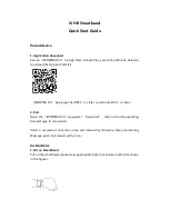
Install the T-Bracket:
The pre-drilled holes in the T-Bracket are designed to allow easy installa-
tion of the bracket onto the bolts that are used to adjust the height of the
footstretcher shoe plate. To mount in this location, simply remove one of
the bolts, slide the mounting bracket onto the bolt in front or behind the
plate, and replace the bolt.
If there is not a bolt already on the footstretcher that you can use, you may
need to drill holes in the footstretcher and secure the docking station with
a stainless steel bolt and nut or screw(s). Be sure your footplate is a solid
material if you are using screws. It may be necessary to insert a small shim
behind the stem of the T-Bracket to support it.
To mount the T-Bracket onto the washbox or cockpit wall, you may use VHB tape to avoid making holes in your
boat. Try to maximize the contact area for the VHB as the stem of the mount-
ing bracket takes a good deal of force when clicking the SpeedCoach into the
mounting dock.
Install the Angle Bracket:
The Angle Bracket is designed to be mounted to the top of a wing rigger or
the deck. The Dual-Lock tape allows you to remove the docking station from
the wing rigger when you derig your boat. It's easiest to leave both pieces of
Dual-Lock attached to the bracket when making the installation.