background image

Safety information

Introduction

Product information

System configuration

Mechanical 

Installation

Electrical Installation

Unidrive M Modular Installation Guide                                                                                                                                                                                 

31

Issue Number: 2                                                       

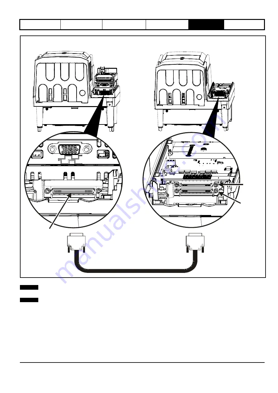
Figure 5-10 Parallel control connections

*Only supplied with follower drive.

N

The parallel cable should be routed according to the rules shown in Figure 6-19

Sensitive signal circuit clearance

on page 72 for the control cable.

N

The screw locks on the parallel cable must be fully tightened.

Paralleling cable*

Input from
master
to follower

Output to
next
follower

Control master pod

Output from
master to
follower

Control follower pod

NOTE

NOTE

Summary of Contents for 09201760D

Page 1: ...Installation Guide Unidrive M Modular Universal Variable Speed AC drive Modular Solutions for induction and permanent magnet motors Part Number 0478 0141 02 Issue 2 www controltechniques com...

Page 2: ...rough increased machine process efficiency reduce raw material consumption and scrap throughout their long working lifetime In typical applications these positive environmental effects far outweigh th...

Page 3: ...fety information It is essential that the warnings are observed and the information considered when working with or designing a system using the drive This map of the user guide helps to find the righ...

Page 4: ...19 4 System configuration 20 5 Mechanical Installation 25 5 1 Safety information 25 5 2 Planning the installation 25 5 3 Terminal cover removal 26 5 4 Mounting of the control master follower standard...

Page 5: ...ty and EMC The assembler is responsible for ensuring that the end product or system complies with all the relevant laws in the country where it is to be used Refer to the User Guide An EMC Data Sheet...

Page 6: ...al limits Drives must not be subjected to excessive physical force 1 5 Access Drive access must be restricted to authorized personnel only Safety regulations which apply at the place of use must be co...

Page 7: ...lectric shock and may be lethal AC supply cables and connections Output cables and connections Many internal parts of the drive and external option units Unless otherwise indicated control terminals a...

Page 8: ...uadrant motor control Multiple controlled rectifier bridges for Minimizing supply current harmonics by drawing 6 12 or 18 pulse supply load currents 2 1 Rectifier The Unidrive M Rectifier is a half co...

Page 9: ...400 V drive Figure 2 3 Size 9E and Inverter schematic 2 4 Size 9D and 10D Inverter The size 9D and 10D is an inverter stage only DC in to AC out If a rectifier is required then an AC input line reacto...

Page 10: ...tput sharing choke must be used on the output of Unidrive M when more than one module is paralleled together Figure 2 6 Single output sharing choke OTLX0X Figure 2 7 Dual output sharing choke OTLX1X F...

Page 11: ...Voltage rating 2 200 V 4 400 V 5 575 V 6 690 V Current A 100A B 1 0 0 0 Reserved Reserved Reserved Conformal coating 0 Standard Brake Transistor B Brake N No Optional Build 09 to 11 AC to AC DC to AC...

Page 12: ...1 For constant torque applications or applications which require a high overload capability or full torque is required at low speeds e g winders hoists The thermal protection is set to protect force...

Page 13: ...125 357 5 283 424 5 495 25 75 100 10203000 360 110 150 396 300 450 525 90 125 Model Normal Duty Heavy Duty Maximum continuous output current Nominal power at 400 V Motor power at 460 V Peak current M...

Page 14: ...100 torque is available down to 4 Hz for a 50 Hz motor Quadratic V F mode The voltage applied to the motor is directly proportional to the square of the frequency except at low speed where a voltage...

Page 15: ...8 9 10 11 12 9E 10E 2 13 14 14 15 18 17 9D 10D 2 15 14 16 17 15 18 14 14 15 16 14 13 2 Rectifier 15 19 15 13 14 19 15 19 13 19 16 14 15 18 17 9A 2 2 Key 1 Rating label 6 Option module slot 3 11 NV med...

Page 16: ...ons Module was built The letters go in alphabetical order starting with A in 1990 B in 1991 C in 1992 etc Example A date code of W28 would correspond to week 28 of year 2013 Model Approvals Input phas...

Page 17: ...t for Normal Duty rating Output current RECT 106 02480 A STDN39 I P 500 690V 50 60Hz 3ph 202A O P 640 1067V 247A Designed in UK Made in U K Serial No 3000005001 Input current Output current Model Inpu...

Page 18: ...9 and must be used with the rectifiers Failure to provide sufficient reactance could damage or reduce the service life of the rectifier or inverter Model Serial number Customer and date code M000 FOLL...

Page 19: ...and 10 Inverter and Rectifier Installation Sheet a safety information booklet the Certificate of Quality and an accessory kit box including the items shown in Table 3 8 Table 3 8 Parts supplied with...

Page 20: ...or a size 9E or 10E module operating on a 3 phase AC supply Figure 4 2 Layout for a size 9A module operating on a 3 phase AC supply Input connections Mains Supply L1 L2 Line reactor Optional EMC filte...

Page 21: ...Installation Electrical Installation Unidrive M Modular Installation Guide 21 Issue Number 2 Figure 4 3 Layout for two size 9A modules operating on a 3 phase AC supply L3 L2 L1 Fuses Fuses Master Foll...

Page 22: ...allation 22 Unidrive M Modular Installation Guide Issue Number 2 Figure 4 4 Layout for two size 9E or 10E modules operating on a 3 phase AC supply L3 L2 L1 Fuses Fuses Master Follower OTLXXX sharing c...

Page 23: ...e M Modular Installation Guide 23 Issue Number 2 Figure 4 5 Layout for a Unidrive M size 9D and 10D module operating on a 3 phase supply PE Input connections Mains Supply L1 L2 Line reactor Optional E...

Page 24: ...4 V 0 V 0 V Fuses Fuses OTLXXX sharing chokes U V W U V W OTLXXX sharing Parallelling cable chokes 9D 10D 9D 10D Current sharing between drives whose motor outputs are connected in parallel When used...

Page 25: ...must meet requirements which can be summarized for larger enclosures as using materials meeting at least UL 94 class 5VB at the point of minimum thickness Air filter assemblies to be at least class V...

Page 26: ...n a classified hazardous area unless it is installed in an approved enclosure and the installation is certified 5 3 Terminal cover removal 5 3 1 Removing the terminal covers Unidrive M size 9 10 D and...

Page 27: ...configuration Mechanical Installation Electrical Installation Unidrive M Modular Installation Guide 27 Issue Number 2 Figure 5 3 Location and identification of terminal covers 9E 10E 9A Output Contro...

Page 28: ...rminal cover undo the screw and lift the terminal cover off as shown When replacing the terminal covers the screws should be tightened with a maximum torque of 1 N m 0 7 lb ft Figure 5 5 Removing the...

Page 29: ...h hammer as shown 1 Pliers can be used to remove the breakouts grasp the relevant break out with pliers and twist it as shown 3 Continue until all the required break outs have been removed 2 Remove an...

Page 30: ...ghted and then removing the two plastic covers 2 Care must be taken when installing master control pod Refer to Figure 5 9 Use the 2 x M6 screws to mount the control master pod to the drive in the pos...

Page 31: ...nections Only supplied with follower drive N The parallel cable should be routed according to the rules shown in Figure 6 19 Sensitive signal circuit clearance on page 72 for the control cable N The s...

Page 32: ...n 32 Unidrive M Modular Installation Guide Issue Number 2 Figure 5 11 Installation of parallel cable management bracket Loosen the ground connection nuts and slide the cable management bracket in the...

Page 33: ...ffect of reducing the temperature within the enclosure The following drawings show the dimensions of the drive and mounting holes for each method to allow a back plate to be prepared 5 5 1 Surface mou...

Page 34: ...lectrical Installation 34 Unidrive M Modular Installation Guide Issue Number 2 Figure 5 13 Surface mounting the Unidrive M size 9D 10D 310 mm 12 21 in 285 mm 11 22 in 773 mm 30 43 in 714 mm 28 11 in 2...

Page 35: ...the Unidrive M size 9A Figure 5 15 Surface mounting the Unidrive M Rectifier 285 mm 11 22 in 310 mm 12 20 in 1108 mm 43 61 in 290 mm 11 42 in 1049 mm 41 31 in 259 mm 10 18 in 26 mm 1 01 in 9mm 0 35 in...

Page 36: ...m configuration Mechanical Installation Electrical Installation 36 Unidrive M Modular Installation Guide Issue Number 2 Figure 5 16 Control master pod dimensions 367 5 mm 14 5 in 346 0 mm 13 7 in 92 5...

Page 37: ...ugh panel mounting the Unidrive M size 9E 10E n5 5 typ 8 places 989 8 259 mm 10 20 in 290 mm 1 1 42 in 327 mm 12 87 in 883 mm 34 76 in 586 mm 23 07 in 406 mm 15 98 in 231 mm 9 09 in 9 0 mm 0 35 in x 4...

Page 38: ...Through panel mounting the Unidrive M size 9D 10D 285 mm 1 1 22 in 310 mm 12 21 in 340 mm 13 39 in 773 mm 30 43 in 190 mm 7 48 in 99 mm 3 90 in 714 mm 28 11 in 693 7 231 mm 9 09 in 406 mm 15 98 in 58...

Page 39: ...48 in 100 mm 3 94 in 1049 mm 41 31 in 259 mm 10 18 in 288 mm 11 34 in 328 mm 12 90 in 9 0 mm 0 35 in x 4 holes 942 mm 37 08 in 734 mm 28 89 in 491 mm 19 32 in 231 mm 9 09 in 5 0 mm 0 21 in x 8 holes...

Page 40: ...ting brackets Kits are supplied separately Table 5 2 Through panel mounting kits Frame size Surface Qty Through panel Qty 10 Rectifier x 2 x 2 Hole size 9 mm 0 35 in x 2 Hole size 9 mm 0 35 in Hole si...

Page 41: ...Forced or convection air flow must not be restricted by any object or cabling Note For EMC compliance 1 When using an external EMC filter one filter is required for each drive 2 Power cabling must be...

Page 42: ...7 in 30 mm 1 18 in Optional braking resistor and overload Locate optional braking resistor external to cubicle preferably near to or on top of the cubicle Locate the overload protection device as requ...

Page 43: ...drive 2 Power cabling must be at least 100 mm 4 in from the drive in all directions A 60 mm 2 362 in Optional braking resistor and overload Locate optional braking resistor external to cubicle prefera...

Page 44: ...rection factor used is for altitude calculation only If the ambient is less than 40 C the drive cannot be over rated The maximum permissible output currents should remain the same as those given at 40...

Page 45: ...ry to achieve desired output current based on altitude calculation and other drive derates e g paralleling derates switching frequency derates ambient derate etc Enclosure design to prevent recirculat...

Page 46: ...4 5 C This shows that with the maximum allowable ambient drive temperature of 40 C the enclosure will overheat Processing results Option 1 If the absolute temperature inside the enclosure is still les...

Page 47: ...drop 5 Make sure Drive inlets are as close to the enclosure air inlet as possible 6 Do not block the inlet and outlets of the drive airflow Keep to best practice spacing between drives and other parts...

Page 48: ...s that are used for mounting should be installed with the nylon washers provided in the kit box to maintain a seal around the screw hole See Figure 5 33 for details regarding IP54 protection It may be...

Page 49: ...unting 50 mm max 1 97 in max 5 mm 0 2 in 253 mm 9 96 in placed centrally along length 817 mm 32 17 in 5 mm 0 2 in 817 mm 32 17 in Backplate Enclosure rear wall A B A B 1 2 3 4 5 6 M6 M8 6 5 4 3 2 1 Ta...

Page 50: ...ith a degree of flexibility external EMC filters have been sourced from two manufacturers Schaffner Fuss Filter details for each drive rating are provided in the tables below Both the Schaffner and Ep...

Page 51: ...System configuration Mechanical Installation Electrical Installation Unidrive M Modular Installation Guide 51 Issue Number 2 Figure 5 36 External EMC filter Table 5 11 Optional external EMC filter det...

Page 52: ...reactor INLX0X 5 10 2 Output sharing chokes Figure 5 38 Single output sharing choke OTLX0X Figure 5 39 Dual output sharing choke OTLX1X For overall dimensions and other details refer to section 6 3 O...

Page 53: ...2 5 11 Electrical terminals 5 11 1 Location of the power control and ground terminals Figure 5 40 Power and ground terminals Unidrive M 9E 10E 9A Rectifier 1 2 3 3 6 4 4 4 8 7 9 8 5 5 4 5 8 9 6 4 9D 1...

Page 54: ...ng tables Model Connection type Torque setting All Plug in terminal block 0 5 N m 0 4 lb ft Model AC terminals High current DC and braking Ground terminal All M10 stud 15 N m M10 stud or nut and bolt...

Page 55: ...in a manner that causes the display to go blank immediately it is possible the capacitors will not be discharged In this case consult Control Techniques or their authorized distributor Equipment suppl...

Page 56: ...2 Unidrive M size 9A power connections See section 6 1 3 Ground connections U V W Motor Optional ground connection DC BR Thermal overload protection device Output connections Input connections Mains...

Page 57: ...24 V supply cable must be connected between the rectifier and the inverter The RJ45 cable carries control signal and start up command signal from the inverter to the rectifier Figure 6 4 Locations of...

Page 58: ...8 The supply ground and motor ground connections to the drive are connected internally by a copper conductor with a cross sectional area given below 9E 10E 75 mm2 9A 9D 10D 120 mm2 Rectifier 128 mm2 F...

Page 59: ...upply unbalance of up to 3 5 negative phase sequence equivalent to 5 voltage imbalance between phases Severe disturbances may be caused by the following factors for example Power factor correction equ...

Page 60: ...3 313 28 5 242 220 205 25 50 1 10402700 4401 0199 OTL404 378 23 9 242 220 205 25 50 1 10403200 4401 0200 Model Current A Inductance H Width W mm Depth D mm Height H mm Weight kg Max ambient temp C Min...

Page 61: ...istor to dissipate regenerative energy from several drives There are limitations to the combinations of drives which can be used in this configuration For further information contact the supplier of t...

Page 62: ...alculate maximum input currents Table 6 10 Size 10 AC Rectifier current and fuse ratings Table 6 11 Cable ratings for size 10 Rectifier Model Symmetrical fault level kA 9A 100 9E 10E 9D 10D Rectifier...

Page 63: ...tage IEC Fuse types IEC class gG Full range breaking capability in general application Slow acting IEC class gR Dual rated semiconductor protection ultra fast acting and cable protection IEC class aR...

Page 64: ...r or shield these cables have a low capacitance and are recommended Cables that do not have an insulating jacket tend to have high capacitance if a cable of this type is used the maximum cable length...

Page 65: ...engths in Table 6 13 and Table 6 16 apply to the sum of the total cable lengths from the drive to each motor It is recommended that each motor is connected through a protection relay since the drive c...

Page 66: ...ve is part of a common DC bus system In parallel systems without the DC bus connected the resistors must be matched to within 5 For high inertia loads or under continuous braking the continuous power...

Page 67: ...Braking Resistor Connections This section details the rules that govern the connection of braking resistors to a parallel application The braking resistor should be connected across the brake and DC...

Page 68: ...tion 6 10 4 Compliance with generic emission standards on page 72 must be followed N The installer of the drive is responsible for ensuring compliance with the EMC regulations that apply where the dri...

Page 69: ...Optional ground connection External controller 0V If the control circuit 0V is to be grounded this should be done at the system controller only to avoid injecting noise currents into the 0V circuit G...

Page 70: ...eld connections at each interruption Encoder connections Use a cable with the correct impedance Use a cable with individually shielded twisted pairs Connect the cable shields to 0 V at both the drive...

Page 71: ...sembled in the standard recommended configuration Table 6 19 Second environment emission compliance Key Unrestricted EN 61800 3 2004 second environment unrestricted distribution For longer motor cable...

Page 72: ...r and shielded motor cable Observe the layout rules given in Figure 6 18 Ensure the AC supply and ground cables are at least 100 mm from the power module and motor cable Figure 6 18 Supply and ground...

Page 73: ...motor cable shield Unshielded wiring to the optional braking resistor s may be used provided the wiring does not run external to the enclosure Ensure a minimum spacing of 300 mm 12 in from signal wir...

Page 74: ...signed for general use within machines and small systems without any special precautions These circuits meet the requirements of EN 61000 6 2 2005 1 kV surge provided the 0 V connection is not grounde...

Page 75: ...m the 0 V of the drive control terminals but it is connected to ground 6 11 2 Unidrive M701 485 serial communications The 485 option provides two parallel RJ45 connectors allowing easy daisy chaining...

Page 76: ...output mode select destination source invert logic select 24 25 26 Relay 1 Source invert 41 42 Drive enable SAFE TORQUE OFF 1 31 10 V User output 1 4 24 V User output 1 Source invert 22 0V common 6 1...

Page 77: ...Jog forward select SAFE TORQUE OFF Drive enable Relay Over voltage category II Drive OK Speed frequency 0V common Analog frequency speed reference 2 4 7 11 9 10 8 Torque active current Analog input 3...

Page 78: ...Pr 01 037 Pr 03 022 or Pr 04 008 in RFC A and RFC S modes 4 ms for open loop mode and all other destinations in RFC A or RFC S modes 7 Analog input 2 Default function Frequency speed reference Type of...

Page 79: ...utput Terminal 25 default function DRIVE RESET input Terminal 26 default function RUN FORWARD input Type Positive or negative logic digital inputs positive logic voltage source outputs Input output mo...

Page 80: ...continuous operating voltage 19 2 Vdc Maximum continuous operating voltage 30 Vdc IEC 26 Vdc UL Minimum startup voltage 21 6 Vdc Maximum power supply requirement 60 W Recommended fuse 4 A 50 Vdc To p...

Page 81: ...ices 2 24 V user output selectable Terminal 2 default function 24 V user output Programmability Can be switched on or off to act as a fourth digital output positive logic only by setting the source Pr...

Page 82: ...V Absolute maximum applied voltage 30 V Logic Threshold 10 V 5 V Low state maximum voltage for disable to SIL3 and PL e 5 V Impedance 4 mA 15 V from IEC 61131 2 type 1 3 3 k Low state maximum current...

Page 83: ...ors with or without marker pulse AB Servo 3 Forward reverse incremental encoders with or without marker pulse FR 2 Forward reverse incremental encoders with UVW commutation signals for absolute positi...

Page 84: ...tion interface and Pr 03 085 is set to a valid source for the encoder simulation output then the P2 position interface will not be available Depending on the device type used on the P1 position interf...

Page 85: ...P1 Position feedback interface Pr 03 038 Connections 1 2 3 4 5 6 7 8 9 10 11 12 13 14 15 AB 0 A A B B Z Z V 0V Th FD 1 F F D D Z Z FR 2 F F R R Z Z AB Servo 3 A A B B Z Z U U V V W W FD Servo 4 F F D...

Page 86: ...FR 3 F F R R Z Z EnDat 4 SSI 5 BiSS 6 DATA DATA CLK CLK Freeze2 Freeze2 None 0 AB Asim Asim Bsim Bsim Zsim Zsim FD Fsim Fsim Dsim Dsim Zsim Zsim FR Fsim Fsim Rsim Rsim Zsim Zsim SSI DATAsim DATAsim CL...

Page 87: ...able Working common mode range 7 V to 12 V Resolver 14 Type 2 Vrms sinusoidal signal Operating Frequency 6 8 kHz Input voltage 0 6 Vrms Common to All Absolute maximum applied voltage relative to 0V 9...

Page 88: ...U C Not used Not used 8 U C Not used Not used AB Servo 3 FD Servo 4 FR Servo 5 SC Servo 12 Type EIA 485 differential receivers Maximum input frequency 512 kHz Line loading Line termination components...

Page 89: ...n components 120 switchable Working common mode range 7 V to 12 V SC EnDat 9 SC SSI 11 Type Differential voltage Maximum Signal level 1 25 V peak to peak sin with regard to sinref and cos with regard...

Page 90: ...68 EMC Compliance with generic emission standards 72 EMC General requirements 69 EMC Variations in the wiring 73 EN61800 3 2004 standard for Power Drive Systems 71 Enclosing drive for high environment...

Page 91: ...SAFE TORQUE OFF function input 1 drive enable 82 SAFE TORQUE OFF function input 2 drive enable 82 SAFE TORQUE OFF drive enable 80 82 Safety Information 6 25 Selecting fan 47 Serial comms lead 75 Supp...

Page 92: ...0478 0141 02...

Reviews: