


EN
English –
7
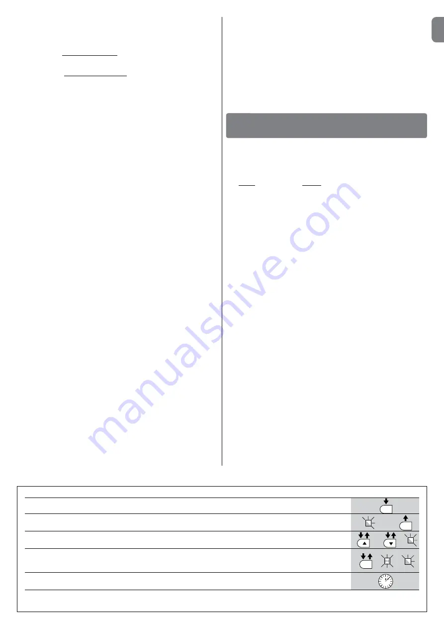
TABLE 5 - Programming procedure (first level functions)
01.
Press and hold down the “
Set
” key for approx. 3 seconds;
02.
Release the key when LED
L1
starts flashing;
03.
Press keys “
s
” or “
t
” to move from the flashing led to the led associated with the function to be modified;
04.
Press “
Set
” to change the status of the function:
(short flash = OFF; long flash = ON)
05.
Wait 10 seconds (maximum time) to exit the programming mode.
Note
– During this procedure, points 03 and 04 need to be repeated when programming other functions to “ON” or “OFF” during the phase itself .
SET
SET
SET
L1
or
3 s
10 s
The control unit has 3 keys
OPEN
(
s
),
STOP
(
Set
),
CLOSE
(
t
) (
Fig. 49
) that
can be used both for controlling the unit during testing and for programming
the available functions .
The programmable functions available are divided into 2 levels and their relative
operating status is displayed by means of the 8 LEDs (
L1
…
L8
) on the control
unit (LED lit = function active; LED off = function not active).
Programming keys:
OPEN
(
s
): the “OPEN” key enables control of pole opening or can be used,
during programming, to move the programming point up .
STOP
(
Set
): the “STOP” key enables the user to stop the manoeuvre; if pressed
for more than 5 seconds, it enables entry to programming mode .
CLOSE
(
t
): the “CLOSE” key enables control of pole closing or can be used,
during programming, to move the programming point down .
CAUTION! – During a manoeuvre (Open or Close) all three keys have
the STOP function: all manoeuvres in progress are stopped.
6.1 - Level one programming (ON-OFF functions)
All level 1 functions are set by default to “
OFF
” and may be modified at any
time as explained in
Table 5
. To check the value corresponding to each LED
see
Table 6
.
IMPORTANT
– The programming procedure has a maximum interval of 10
seconds admissible between the activation of one key and the next. When this
time interval elapses, the procedure quits automatically, saving the changes
made up until that time .
CONTROL UNIT PROGRAMMING
6
each size, in reflective material (e.g. mirror or white gloss paint) and three
sides in opaque material (e .g . black matt paint) . To test the photocells posi-
tioned at 50 cm from the ground, the parallelepiped must be placed on the
ground or raised at 50 cm in the case of photocells placed at 1 m from the
ground .
When testing one pair of photocells, the test specimen must be positioned
exactly at the centre of the pole with the 20 cm sides facing the photocells
and moved along the entire length of the pole (
Fig. 46
) .
When testing two pairs of photocells, the test must first be performed
individually for each pair of photocells, using one test specimen, and then
repeated using two test specimens .
Each test specimen must be positioned laterally with respect to the centre
of the pole, at a distance of 15 cm sides and then moved along the entire
length of the pole (
Fig. 47
) .
During these tests, the test specimen must be read by the photocells in any
position along the entire length of the pole .
7
Ensure there is no interference between the photocells and other devices,
by intercepting the optic axis joining the two photocells by means of a cyl-
inder (diameter 5 cm, length 30 cm,
Fig. 48
): pass the cylinder first close to
the TX photocell, then close to the RX and lastly at the centre between the
two .
Ensure that in all cases the device engages, changing from the active
status to alarm status and vice versa, and that the envisaged action is gen-
erated in the control unit (for example movement inversion in the Closing
manoeuvre) .
8 Check protection against the risk of lifting:
on automations with verti-
cal movement, it must be ensured that there is no risk of lifting . This test can
be performed as follows: hang a weight of 20 kg mid-way along the pole
(for example, a sack of gravel), activate an Opening manoeuvre and ensure
that during operation the pole does not exceed the height of 50 cm from
the closing position. If the pole exceeds this height, reduce the motor force
(see chapter 6 - Table 7) .
9
If hazardous situations generated by the moving poles are protected by
means of impact force limitation, measure the force as specified in the
standard EN 12445. If motor force control is used as auxiliary function with
the system for reduction of impact force, test and identify the setting that
obtains the best results .
10 Check efficiency of the release system:
place the pole in the Closing
position and manually release the gearmotor (see paragraph 3 .6) ensuring
that there is no difficulty with this procedure. Ensure that the manual force
required to move the pole on opening is no greater than 200 N (approx. 20
kg); the force is measured perpendicular to the pole and at 1 m from the
rotation axis. Lastly, ensure that the key required for manual release is avail-
able in the vicinity of the automation .
11 Power supply disconnection system check:
by using the power dis-
connect device, and disconnecting any buffer batteries, ensure that all leds
on the control unit are off and that the pole remains stationary when any
commands are sent. Check efficiency of the locking device to prevent inad-
vertent and/or unauthorised reconnection .
5.2 - Commissioning
Commissioning can only be performed after positive results of all test
phases. Partial or “makeshift” commissioning is strictly prohibited.
1
Compile and provide the automation owner with the “
CE Declaration of
conformity - Appendix I
”, at the end of this manual, in the removable sec-
tion .
2
Compile and provide the automation owner with the form “
Operation
Manual
” at the end of this manual, in the removable section .
3
Compile the form “
Maintenance schedule
” containing all maintenance
instructions for all devices in the automation and forward it to the owner .
In the case of X-Bar, this form is present at the end of this manual, in the
removable section .
4
Before commissioning the automation, ensure that the owner is adequately
informed of all associated risks and hazards .
5
Permanently affix on the pole the label in the pack regarding the gearmotor
manual release and locking operations .
6
ONLY for installations NOT IN CONFORMITY with the criteria stated in
chapter 1.3.1 of this manual: produce the technical documentation of
the automation, which must include the following documents: an overall
drawing of the automation, the wiring diagram of all connections made, an
assessment of all risks present and relative solutions adopted (see forms to
be compiled on the website
www.niceforyou.com
), declarations of con-
formity of manufacturer of all devices used (for X-Bar see appendix II) and
the declaration of conformity compiled by the installer .
Affix a dataplate on the barrier, specifying at least the following data: type of
automation, name and address of manufacturer (responsible for commis-
sioning), serial number, year of construction and CE mark .
Summary of Contents for X-Bar
Page 2: ......
Page 3: ...I 1 A B D C D B 3 2 179 5 mm 300 mm 1146 mm 826 mm 3000 mm b a l d e c i g f h...
Page 4: ...II 5 A B C 4...
Page 5: ...III 9 10 90 6 A C B 7 8 B A...
Page 6: ...IV 14 A B 15 A B 11 A B 12 13 A B...
Page 7: ...V 18 17 16 A B...
Page 8: ...VI 20 21 OK O O 19 A B C D...
Page 9: ...VII 22 A 2cm 1cm 23 A B C D...
Page 10: ...VIII 24 26 27 180 25 C C A B...
Page 12: ...X Op en St op Se t Cl os e Fuse 1AT L1 L2 L3 L4 L5 L6 L7 L8 34 35 36 A A B...
Page 13: ...XI STOP 37 A B 38 A B C D...