7
GB
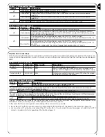
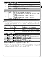
Jumper Position
Description
Connected
Phototest input connected to the Phototest output of the control unit.
Phototest input connected to the S.C.A. output of the control unit; or the input Phototest
Disconnected disconnected if the control unit is not fitted with Phototest or output SCA (Caution: possible
only with JP3 on TX deactivated)
The interruption of the infrared beam causes the PHOTO contact to open.
The activation of the sensitive edge causes the ALT contact to open and the ALT1 after 1.5
seconds.
The interruption of the infrared beam causes the PHOTO contact to open.
The activation of the sensitive edge causes the ALT contact to open and the ALT1 after 1.5
seconds.
To be used in control units that do not foresee the inversion when ALT cuts in.
Disconnected
JP2
Jumper Position
Description
Connected
Transmitter power suitable for gates up to 15 meters.
Disconnected Transmitter power suitable for gates up to 7 meters.
Connected
Change over to SLOW transmission after 10 seconds from the end of the manoeuvre
(see JP3).
Disconnected Change over to SLOW transmission after 90 seconds from the end of the manoeuvre
(see JP3).
Connected
Change over to SLOW transmission at the end of the manoeuvre.
Disconnected Never changes over to SLOW transmission but remains in the FAST mode.
Table 1: TX transmitter jumpers
JP1
JP2
JP3
Table 2: RX receiver jumpers
JP1
Connected
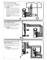
3.3) Electrical connections
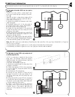
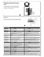
This chapter describes the electrical connections and illustrates various possible connection layouts based on the type of con-
trol unit used on the automation system. If in doubt, do not use the product and contact the Nice technical assistance depart-
ment.
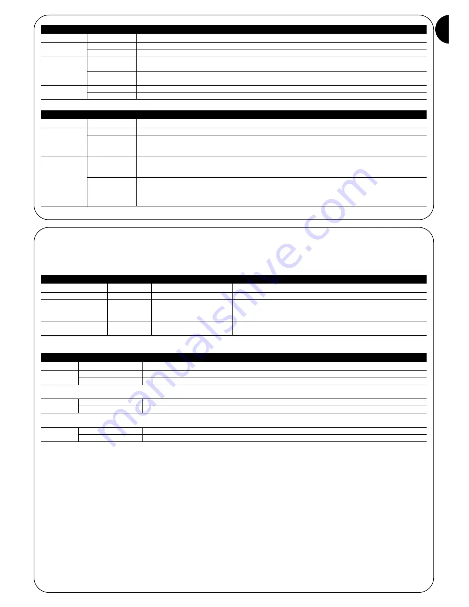
Connection
Cable type
Max. length
Description
12÷24V
2x0,5mm
2
30m
AC or DC receiver power supply
Phototest
2x0,25mm
2
30m
Start of manoeuvre test input, which can be connected to
the AC or DC voltage and is not limited by the power supply
terminals.
Output contacts
2x0,25mm
2
30m
Output relay contacts; normally closed (NC) when the receiver
is powered and active (see table 4)
Table 3: List of connections
Output
Relay contact
Description
PHOTO
Closed
There are no obstacles and the TX data is received correctly.
Open
Obstacles are present and the TX data is not received.
The PHOTO output (Photocell) must be connected to the control unit input that causes the inversion of the manoeuvre,
which is normally used by the D type presence sensor.
ALT
Closed
No pressure is applied to the sensitive edge connected to the TX.
Open
Pressure is applied to the sensitive edge connected to the TX.
The ALT output must be connected to the control unit input that causes the stop and eventual inversion of the manoeuvre,
which is normally used by PSPE pressure sensitive safety devices.
ALT1
Closed
No pressure is applied to the sensitive edge connected to the TX.
Open
After 1.5 seconds if pressure is applied to the sensitive edge connected to the TX.
The ALT1 output must be connected to the second input of the control unit that causes the stop and eventual inversion of the
manoeuvre, which is normally used by PSPE pressure sensitive safety devices.
In the event that this second input is not available on the control unit it is possible:
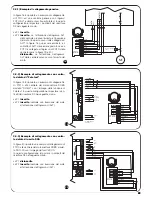
• to use the ALT1 output to control a relay of suitable capacity that directly cuts the power to the motor (see figure 18).
• not to use the ALT1 output and disconnect the JP2 on the RX, in this way when the sensitive edge is activated the PHOTO
contact is opened which also guarantees the failsafe category 3.
Table 4: RX output description


