6
3.
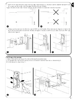
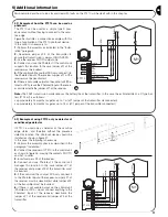
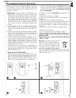
Assemble the transmitter on the mobile leaf as shown in figure 11.
4
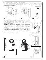
. Connect the 8,2K
Ω
, constant resistance type sensitive edge on the transmitter as shown in figure 12. The resistance on the
TX terminals is removed and used as a termination on the sensitive edge or does not need to be used if the sensitive edge
already has a terminating resistance.
If the sensitive edge has an output with 2 separate NC contacts, it can be connected
as shown in figure 13 placing the 8,2K
Ω
resistance in series between the two con-
tacts. Make sure that the sensitive edge complies with the failsafe category 3 accord-
ing to the EN 954-1 standard.
Warning:
do not use sensitive edges that have only one NC type contact because
they do not have the necessary failsafe category required by the said standard.
5.
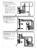
Carry out the electrical connections following that which is indicated in the control
unit instructions manual. Also see the connection examples in chapter 3.3 “Electrical
connections”.
6
. Direct the lenses as shown in fig. 14 in order to obtain the correct alignment
between the TX and RX. The correct alignment will be verified in chapter 4 “Testing”.
7.
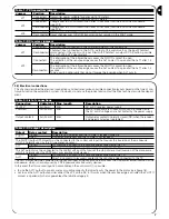
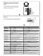
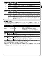
Program the jumpers on both the TX and RX (see figure 15) for the desired operation
following that indicated in table 1 and 2. Position the jumpers that are not used in their
locations for future use (see figures 16 and 17)
PHOTOTEST
PHOTOTEST
0Vac/dc
24Vac/dc
RX
TX
L
L1
L2
L3
L4
JP1
JP2
JP1
JP2
JP3
-
+
ALT
COM
ALT1
COM
PHOTO
COM
Sensitive Device
3,6 V
11
12
13
14
16
17
15


