


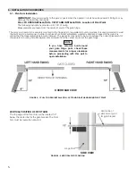


Figure 5-1
Left And Right Hand Swing Pivot Point
5
Figure 5-2
Vertical Pivot Position
5
Figure 5-3
Pivot Arm Installation
6
Figure 5-4
Hinge Post
6
Figure 5-5
Actuator Mounting
6
Figure 5-6
Control Box Mounting
7
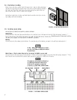
Figure 5- 7
Incoming Power Wiring
7
Figure 5-8
Manual Release Handle
8
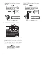
Figure 5-9
Titan Actuator Wiring
8
Figure 5-10
Titan Actuator Wiring
8
Figure 5-11
Titan Actuator Wiring (Standard)
8
Figure 5-12
Titan Actuator Wiring (Push To Open)
8
Figure 5-13
Actuator Motor Leads
9
Figure 5-14
Actuator Motor
Leads
9
Figure 5-16
Gate Bracket Mounting
9
Figure 5-15
Limit And Motor Connection To The Board
10
Figure 5-17
Limit Switch Adjustment
10
Figure 5-19
Learning Mode - Open Limit
10
Figure 5-20
Learning Mode - Closed Limit
10
Figure 6-1
Board Outputs
12
Figure 6-2
Board Inputs
12
Figure 6-3
Communication Buses
13
Figure 7-1
Equipment Safety Warnings
14
Figure 9-1
Fire Department Input
15
Figure 9-2
Magnetic Lock Wiring (Example)
15
Figure 9-3
Guard Station Inputs
15
Figure 9-4
Exit And Edge Inputs
15
Figure 10-1
Radio Receiver
16
Figure 12-1
Layout For Inground Loops
17
Figure 12-2
Layout For Photocells
17
Figure 14 -1
Manual Release
19
19
Figure 13-3
Manual Release Disable
LIST OF FIGURES
Summary of Contents for Titan 912L
Page 2: ...TABLE OF CONTENTS...


