


8
5.6 - Titan actuator wiring
Actuator Limit Switch And Smart Sensor Wiring
Actuator Limit Switch And Smart Sensor Wiring
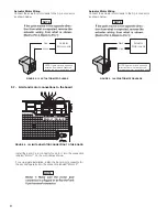
Connect the actuator cable to the 5-pin connector as shown
below. These connections enable the limit switch and smart
sensor inputs into the gate controller.
Connect the actuator cable to the 5-pin connector as shown
below. These connections enable the limit switch and smart
sensor inputs into the gate controller.
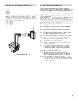
TITAN ACTUATOR WIRING (STANDARD)
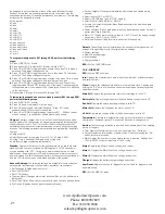
TITAN ACTUATOR WIRING (PUSH TO OPEN)
Terminal Block
For Harness
Connections
Connect the wiring to the actuator terminal block as shown.
Limits and
Encoder
White: Close limit
Orange: Open Limit
Green: Limit Common
Yellow: Encoder Signal
Blue: Encoder Power
Green
Yellow
Blue
Orange
White
Limits and
Encoder
White: Close limit
Orange: Open Limit
Green: Limit Common
Yellow: Encoder Signal
Blue: Encoder Power
Green
Yellow
Blue
White
Orange
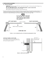
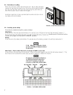
With the release handle up, remove the screws from the limit cover and remove the cover. On the bottom of the actuator
loosen the strain relief nut and insert the wire into the actuator housing. The connections are on the top of the atuator behind
the limit assembly.
Using the supplied key, unlock the manual release handle. Lift upwards on the release handle as
s
hown.
EXTEND LIMIT
COMMON
ENCODER
ENCODER
MOTOR -
MOTOR +
RETRACT LIMIT
NOTE
WHITE
ORANGE
YELLOW
BLUE
BLACK
RED
GREEN
FIGURE 5 - 8 MANUAL RELEASE HANDLE
FIGURE 5 - 9 TITAN ACTUATOR WIRING
FIGURE 5 - 10 TITAN ACTUATOR WIRING
FIGURE 5 - 11 TITAN ACTUATOR WIRING (STANDARD)
FIGURE 5 - 12 TITAN ACTUATOR WIRING (PUSH TO OPEN)
1 2
2
3
3
1
4
4
5
5
ll
l
I
l
ll
l
l
Summary of Contents for Titan 912L
Page 2: ...TABLE OF CONTENTS...


