

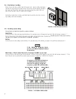


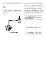


10- RADIO RECEIVER CONNECTION (THIRD PARTY)
38 12V
39 OPEN
40 CLOSE
41 GND
The customer supplied radio receiver allows the gate operator to be operated
via remote, such as wireless key-card readers or user remote controls.
Connecting the Open (39) and Close (40) pins together with a receiver
to control the gate in the following sequence:
Press - Gate Open
Press - Gate Stop
Press - Gate Close
Press - Gate Stop
11 - INSPECTION AND OPERATION
Proper inspection of all equipment is required to ensur e continuous
functionality, safety and to ensure reliable operation in all weather conditions.
Inspect electrical assemblies and wiring installations for damage, general
condition, and proper functioning to ensure the continued satisfactory
operation of the electrical system. Adjust, repair, overhaul, and test electrical
equipment and systems in accordance with the recommendations and
procedures in the gate operator system and/or component manufacturer’s
maintenance instructions.
Replace components of the electrical system that are damaged or defective
with identical parts, with manufacturer’s approved equipment, or its
equivalent to the original in operating characteristics, mechanical strength,
for and checks to be performed are listed below:
12V Power
Normally Open
Common
Ground
FIGU
R
E 10-1 RADIO RECEIVER
16
Damaged, discolored, or overheated equipment, connections, wiring,
bearing caps and installations.
Excessive heat or discoloration at high current carrying connections.
(look for bluing or heat affected metal).
Misalignment if electrically driven equipment. (Causes strain on
pulley assemblies and bearings).
Poor electrical bonding (broken, disconnected or corroded bonding
strap) and grounding, including evidence of corrosion.
Dirty equipment and connections. Clean equipment and connections.
Improper, broken, inadequately supported equipment, wiring and
conduit, loose connections of terminals, and loose ferrules.
Poor mechanical or weld joints. Broken welds.
Condition of circuit breaker and fuses. Ensure that they are of the
correct type and amperage.
Insufficient clearance between exposed current carrying parts
and ground or poor insulation of exposed terminals. All exposed
connections must be covered (prevent arcing between exposed
parts, and electrical shock).
Broken or missing wire, connectors, etc.
Operational check of electrically operated equipment such as
motors, inverters, generators, batteries, lights, protective devices,
etc. Ensure proper functionality of all systems during inspections.
Ensure safety placards and warning signs are present as specified
within this document. Ensure proper functionality of all safety devices
as specified. Non-functioning or malfunctioning safety devices should
be replaced immediately.
Summary of Contents for Titan 912L
Page 2: ...TABLE OF CONTENTS...


