


Safety information
This manual describes installation and service proced-
ures for implementation by specialists.
The manual must be left with the customer.
Symbols
NOTE
This symbol indicates danger to person or ma-
chine .
Caution
This symbol indicates important information
about what you should consider when installing
or servicing the installation.
TIP
This symbol indicates tips on how to facilitate
using the product.
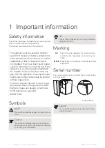
Marking
The CE mark is obligatory for most products
sold in the EU, regardless of where they are
made.
CE
Classification of enclosure of electro-technical
equipment.
IP X1B
Serial number
The serial number can be found at the top right inside
the front hatch.
LEK
Serial number
LEK
Caution
You need the product's serial number for servi-
cing and support.
NIBE GV-HR 120-400
Chapter 1 | Important information
4
1 Important information
This
appliance
can
be
used
by
children
aged
from
8
years
and
above
and
persons
with
reduced
physical,
sensory
or
mental
capabilities
or
lack
of
experience
and
knowledge
if
they
have
been
given
super-
vision
or
instruction
concerning
use
of
the
appliance
in
a
safe
way
and
understand
the
hazards
involved.
Children
shall
not
play
with
the
appliance.
Cleaning
and
user
maintenance
shall
not
be
made
by
children
without
supervision.
This is an original manual. It may not be
translated without the approval of NIBE
.
Rights
to
make
any
design
or
technical
modifications
are
reserved.
©NIBE
2021.


