


NOTE
If the supply cable is damaged, only NIBE, its
service representative or similar authorised
person may replace it to prevent any danger
and damage.
• To prevent interference, sensor cables to external
connections must not be laid close to high voltage
cables.
• The minimum area of communication and sensor
cables to external connections must be 0.5 mm² up
to 50 m, for example EKKX, LiYY or equivalent.
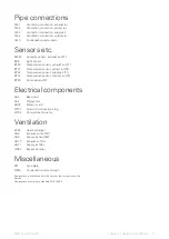
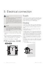
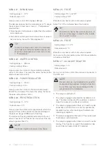
For electrical wiring diagram, see
PCB overview (AA2)
AA2-L2
AA2-L1
Supply
GV-HR 120 is connected to a earthed single-phase wall
socket or a permanent installation. For permanent install-
ations, GV-HR 120 must be preceded by a circuit
breaker with at least a 3 mm breaking gap.
Display
GV-HR 120 is supplied with an enclosed display (AA4),
which contains a room sensor (BT50). The room sensor
is primarily used to control any re-heater, if one is in-
stalled.
Install the display in a neutral location where the set
temperature is required.
A suitable location is on a free inner wall in a hall approx.
1.5 m above the floor. It is important that the sensor is
not prevented from measuring the correct room temper-
ature, for example by being located in a recess, between
shelves, behind a curtain, above or close to a heat
source, in a draught from an external door or in direct
sunlight. Closed radiator thermostats can also cause
problems.
The display contains a light sensor (BR2) that regulates
its brightness; for this reason, it should not be placed
close to a lamp.
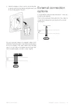
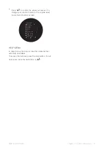
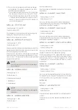
1.
Fit the display mount on the wall.
Z1
Z2
Z3
Z4
C1
C2
C3
C4
UN
NIBE GV-HR 120-400
Chapter 5 | Electrical connection
14
5 Electrical connection
NOTE
All electrical connections must be carried out
by an authorised electrician.
Electrical installation and wiring must be carried
out in accordance with the stipulations in force.
ERS S10 must not be powered during installa-
tion.


