


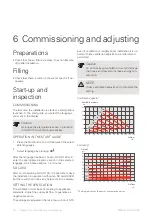


General ventilation
connections
• Ventilation installation must be carried out in accord-
ance with current norms and directives.
• Provision must be made for inspection and cleaning
of the duct.
• The air duct system must be a minimum of air tight-
ness class B.
• To prevent fan noise being transferred to the ventila-
tion devices, install silencers in suitable locations in
the duct system.
• The extract air and outdoor air ducts are insulated us-
ing diffusion-proof material (at least PE30 or equival-
ent) along their entire lengths.
• Ensure that the condensation insulation is fully sealed
at any joints and/or at lead-in nipples, silencers, roof
cowls or similar.
• The air must be routed to the outdoor air duct through
an outer wall grille in the facade. The outer wall grille
must be installed so that it is protected from the
weather and must be designed so that no rainwater
and/or snow can penetrate the facade or follow the
air into the duct.
• When positioning the outdoor air and extract air
hood/grille, bear in mind that the two air flows must
not short circuit to prevent the extract air from being
drawn into GV-HR 120 again.
• A duct in a masonry chimney stack must not be used
for extract air or outdoor air.
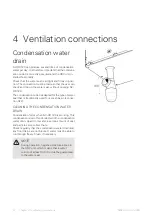
NOTE
To ensure a sealed connection to GV-HR 120,
the supplied hose clips must be used for con-
necting the air ducts.
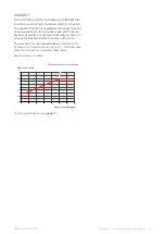
EXHAUST AIR DUCT /KITCHEN FAN
Exhaust air duct (kitchen fan) must not be connected to
GV-HR 120.
To prevent food vapour being transferred to GV-HR 120
the distance between the kitchen fan and the exhaust
air device must be considered. The distance should not
be less than 1.5 m, but this can vary between different
installations.
Always use a kitchen fan when cooking.
Ventilation flow
Connect GV-HR 120 so that all the exhaust air, except
kitchen duct air (kitchen fan), passes through the heat
exchanger (EP26) in the product.
The ventilation flow must comply with the applicable
national standards.
The supply air flow must be lower than the exhaust air
flow to prevent over pressure in the house.
Set the ventilation capacity in the HRV unit’s menu
system (Service menu, menu 10-15).
Adjusting ventilation
To obtain the necessary air exchange in every room of
the building, the exhaust air valve and the supply air inlet
as well as the fans in the HRV unit must be correctly
positioned and adjusted.
Immediately after installation adjust the ventilation so
that it is set according to the projected value of the
house.
Incorrect adjustment of the ventilation may lead to re-
duced installation efficiency and thus poorer operating
economy, a poorer indoor climate and moisture damage
in the building.
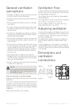
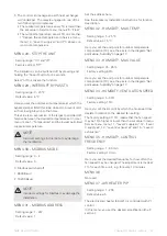
Dimensions and
ventilation
connections
900
44
600
4 x Ø160
G32
308
146
146
278
188
146
612
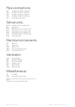
Exhaust air
Outdoor air
Extract air
Supply air
13
Chapter 4 | Ventilation connections
NIBE GV-HR 120-400


