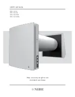
Nibe DVC 10-50 User Manual Download Page 14

www.nibe.com

14

DVC 10-50 (W)

Turning unit ON/OFF 

Party mode. 

Activation of the high speed 

timer (by default for 4 hours). 

Night mode. 

Activation of the low speed timer 

(by default for 4 hours). 

Speed selection 

Ventilation mode 

The unit operates in the supply or 

extract mode at set speed. 

Regeneration mode 

In this mode the fan rotation 

direction changes to opposite every 

70 seconds. This operation mode 

enables heat recovery.

The speed selection sequence is 

follows: 

low-medium-high 

speed-Off. 

Buttons on 

the unit casing 

Remote control 

VENTILATOR CONTROL

The ventilator is operated with the remote control or the buttons on the 

side part of the indoor unit, see the picture on the right. 

In case of series connection or parallel connection of several ventilators 

the signal from a control unit is received by the Master unit only. 

OPERATION OF THE VENTILATOR WITH THE BUTTONS ON THE INDOOR UNIT 

The speed selection sequence is as follows: low-medium-high-OFF. 
All the units integrated in a single network operate according to the speed settings of the Master unit.

I:

 permanent glowing of the lamp indicator indicates operation of the unit with low speed. 

Blinking of the lamp indicates activation of the low speed mode timer. 

I

 and 

II: 

permanent glowing of the lamp indicators I and II indicates operation of the unit with medium speed. 

I, II

 and 

III:

 permanent glowing of the lamp indicators I, II and III indicates operation of the ventilator with the medium speed. 

Blinking of the lamp indicators I, II and III indicates activation of the party mode timer or the turn-off delay timer triggered by any connected 
external sensors or the integrated humidity sensor. 

Regeneration mode. 


The fan rotation direction changes to opposite every 70 seconds. This mode enables heat recovery.

Ventilation mode. 

DVC 10-50(L)
The ventilator operates in the supply or extract mode with a set speed. The fan rotation direction depends on DIP-switch positioning setting 
(extract mode by default). 
DVC 10-50W(L)
The ventilator operates in the supply or extract mode with a set speed. The fan rotation direction depends on PC setting (extract mode by default).

DVC 10-50W(L)
No glowing of the indicator lamps «Regeneration» and «Ventilation» indicates forced operation of the ventilator in the supply mode. This mode may be activated via the 
mobile application only.

Filter

Filter replacement indicator. 90 days after installation of the cartridge the filter replacement indicator starts glowing (in case of non-sop 
operation). In this case replace or clean the filters as described in Maintenance section. 
DVC 10-50(L)
In case of a series connection the indicator of the first ventilator is permanently on. 
The filter timer is reset once the cartridge socket connector is disconnected from the circuit board. 
DVC 10-50W(L)
After replacement of the filters reset the timer using the DIP switch, the mobile application or PC application. 

Alarm

Emergency shutdown indicator. 
Permanent glowing of the Alarm indicator of the Master unit indicates an alarm in the network of the connected ventilators. Its blinking indicates 
shutdown of a specific ventilator in the network. 
In case of an emergency shutdown of a ventilator the defective ventilator is marked with the blinking Alarm indicator. All the connected ventilators 
are also stopped. 

Master

Permanent glowing of the lamp indicator indicates the leading unit in the network (Master unit). Only for DVC 10-50W(L): blinking of the indicator 
means it is a driven unit (Slave) and it has no connection to the Master unit. 
No glowing of the lamp indicator means that this ventilator is a Slave unit and it is connected to the Master unit. 

DVC 10-50W(L)

Synchronous blinking of all the lamp indicators on the casing of the ventilator means activated setup mode via a PC. In this case the fan shuts down. 

Summary of Contents for DVC 10-50

Page 1: ...USER S MANUAL Heat recovery single room reversible ventilator DVC 10 50 DVC 10 50L DVC 10 50W DVC 10 50WL...

Page 2: ...eration NIBE DVC 10 hereinafter the unit as mentioned in the Safety Requirements and Manufacturer s Warranty sections as well as in warnings and information blocks CONTENTS SAFETY REQUIREMENTS Safety...

Page 3: ...bstances in close proximity to the unit When the unit generates unusual sounds odour or emits smoke disconnect it from power supply and contact the Seller Do not open the unit during operation Do not...

Page 4: ...nces toxic substances dust pathogenic germs THE UNIT MAY NOT BE OPERATED BY CHILDREN OR PERSONSWITH REDUCED PHYSICAL MENTAL OR SENSORY CAPACITIES OR LACKINGTHE APPROPRIATETRAINING THE UNIT MUST BE INS...

Page 5: ...Transported air temperature C F from 30 22 to 50 122 Noise level 1 m dB A Sones 20 27 30 20 27 30 Noise level 3 m dB A Sones 11 18 21 11 18 21 Noise level attenuation dB A Sones 42 42 Heat recovery e...

Page 6: ...rol board and basic controls on the side wall of the indoor unit Sound absorbing material Prevents ingress of outer noise into the room Outer ventilation hood Prevents ingress of water and foreign obj...

Page 7: ...erator it heats and moisturizes the regenerator transferring up to 97 heat energy In 70 seconds as the ceramic regenerator gets warmed the unit is switched to the air supply mode Cycle II Fresh intake...

Page 8: ...wedges 0 3 mm 0 1 8 Fill the gap between the air duct and the wall with mounting foam A Polystyrene wedge min 3 mm Install the air duct in the wall in such a way as shown on the left Install the air...

Page 9: ...detach the front part of the indoor unit from its back part Prior to mounting the front panel make sure that the thermal actuator rod is in the lowest position and the light indicator is at least two...

Page 10: ...e front part of the indoor unit 9 Roll the sound absorbing layer to match the air duct diameter with the protecting paper layer outside Do not remove the paper layer Insert the sound absorbing roll in...

Page 11: ...the electric connections Connect the wires to the terminal block located on the control board in compliance with the wiring diagram and terminal designations EXTERNAL WIRING DIAGRAM DVC 10 50 L DVC 10...

Page 12: ...aster Slave 1 Slave N VENTILATOR SETUP DVC 10 50 L DVC 10 50W L Open the rubber cover DIP switch under the cover 1 2 3 4 5 6 7 8 ON DIP 1 2 3 4 DIP switch and USB socket under the cover Prior to opera...

Page 13: ...80 3 4 5 3 4 5 3 4 5 3 4 5 3 4 5 3 4 5 Turn off delay timer After activation of the humidity sensor or a connected external device the ventilator goes to the high speed After return of the humidity an...

Page 14: ...The ventilator operates in the supply or extract mode with a set speed The fan rotation direction depends on DIP switch positioning setting extract mode by default DVC 10 50W L The ventilator operate...

Page 15: ...DIP switch positioning extract mode by default Party mode the timer activates operation of the unit with the high speed for a set time period 4 hours by default The setting may be edited during setup...

Page 16: ...o disable the function uncheck Available OFF device Direction setting rotation direction of the fan in the Ventilation mode This parameter sets the fan rotation direction in the Regeneration mode too...

Page 17: ...50W L Emergency shutdown of all the ventilators happens if the fan shutdown lasts above 5 seconds In case of emergency shutdown of any ventilator in a network all the other ventilators also stop Alarm...

Page 18: ...peed by default for 8 hours The timer setting is set during setup of the ventilator via a PC or the mobile application Party mode high speed timer activation by default for 4 hours The timer setting i...

Page 19: ...the network The Slave unit responds to a signal from the Master unit only Any other signals from other controls are ignored In this mode the ventilators ignore any other signals from the sensors In c...

Page 20: ...e Select a required device from the dropdown list 1 Select Master for required device mode 2 Select No Wi Fi router for the connection type 3 Open the tab Wi Fi 4 Select the type of security for the M...

Page 21: ...ttings of the Master unit and set the unit up for operation according to the diagram No 1 CONFIGURING THE UNIT IN SLAVE MODE ACCORDING TO THE DIAGRAM NO 1 1 4 5 7 8 9 6 10 11 2 3 Start the software at...

Page 22: ...aster unit 9 It must be consistent with the IP address of the router This parameter enables coordinated operation of the ventilator with a cloud server through internet Apply and save the selected par...

Page 23: ...le manual assigning of the IP address for the Slave unit The assigned address must match the current network and be unique Detection of a free IP address is described below Apply and save the selected...

Page 24: ...Enter the connection name 7 Press the button 9 to confirm 2 1 3 4 6 5 8 9 7 MASTER UNIT DEMO MODE This mode is for temporary use i e demonstration of the unit operation in a sales shop No connection t...

Page 25: ...e mobile device Open the page of the home connection 1 2 in the program menu Select the required connection 3 Activate the control function through the could server 4 2 1 4 3 Note if this function is...

Page 26: ...3 to enter the account 1 2 3 Adding new connection Press the button 1 to add the new connection at the page of connection through the cloud server Enter the connection name 2 Enter ID number of the M...

Page 27: ...emains the same To open the air duct pull the front panel through the specially designed recessions The fan automatically starts operating according to the actual speed setting Air duct blocking Air d...

Page 28: ...l If the thermal actuator rod is up please wait about 2 minutes until it goes down Attention Please make sure the thermal actuator rod is in lower position during re installation of the front panel 2...

Page 29: ...ing is allowed The filter rated service life is 3 years Even regular technical maintenance may not completely prevent dirt accumulation on the regenerator and the fan Clean the regenerator regularly t...

Page 30: ...ng or the outer ventilation hood Tighten the screws of the unit or the outer ventilation hood TROUBLESHOOTING STORAGE ANDTRANSPORTATION REGULATIONS Store the unit in the manufacturer s original packin...

Page 31: ...d the brand name with the information stated on the unit packing and in the user s manual User s failure to ensure timely technical maintenance of the unit External damage to the unit casing excluding...

Page 32: ...to certify acceptance of the complete unit delivery with the user s manual The warranty terms are acknowledged and accepted Customer s Signature Seller s Stamp Seller s Stamp Installation Company Stam...

Page 33: ...www nibe com 33 NOTES...

Page 34: ...www nibe com 34 DVC 10 50 W NOTES...

Page 35: ...www nibe com 35 NOTES...

Page 36: ...NIBE155EN 01...

Reviews: