NI ELVIS RIO User Manual Download Page 5

Nominal Range is the absolute value in volts of the full, peak-to-peak nominal range of
the channel, and
Resolution is the resolution of the ADC or DAC in bits (Resolution = 12)

For AI and AO channels on the MXP connectors,

LSB Weight = 5 � ÷ 2

12

= 1.221 ��

Maximum Reading = 4095 × 1.221 �� = 4.999 �

DIO Lines

The NI ELVIS RIO CM provides 3.3 V general-purpose DIO lines on the MXP connectors.

DIO <13..0> on the MXP have 40 kΩ pull-up resistors to 3.3 V, as shown in the following
figure.

Figure 5. DIO Lines with 40 k

Ω 

Pull-up Resistors to 3.3 V

40 k

Ω

DIO/CS

+3.3 V

FPGA

Bus Switch

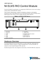
DIO <15..14> on the MXP have 2.2 kΩ pull-up resistors to 3.3 V, as shown in the following
figure.

Figure 6. DIO Lines with 2.2 k

Ω 

Pull-up Resistors to 3.3 V

2.2 k

Ω

FPGA

Bus Switch

DIO/SCL/SDA 

+3.3 V

You can program all MXP DIO lines individually as inputs or outputs. Secondary digital
functions include SPI, I

2

C, PWM, and quadrature encoder input.

Note


For information about configuring the behavior of the DIO lines, visit

ni.com/info

 and enter the Info Code 

elvisriocmhelp

.

When a DIO line is floating, it floats in the direction of the pull resistor. A DIO line may be
floating in any of the following conditions:

When the NI ELVIS RIO CM device is starting up.

When the line is configured as an input.

When the NI ELVIS RIO CM device is powering down.

You can add a stronger resistor to a DIO line to cause it to float in the opposite direction.

NI ELVIS RIO CM User Manual

  | 

© National Instruments

  | 

5

Summary of Contents for ELVIS RIO

Page 1: ...a USB connection Figure 1 NI ELVIS RIO CM Features 1 2 6 5 4 8 7 11 10 12 3 9 13 1 Power LED 2 Status LED 3 LED0 4 LED1 5 LED2 6 LED3 7 Button0 User Button 8 Reset Button 9 USB Host Port 10 Workstati...

Page 2: ...Button0 Watchdog Status LED MXP Connector Pinout AO0 AO1 AGND DGND UART RX DGND UART TX DGND DIO11 ENC A DGND DIO12 ENC B DGND DIO13 DGND DGND DIO14 I2C SCL DIO15 I2C SDA 5V AI1 AI3 AI2 DIO1 DIO2 DIO3...

Page 3: ...RT lines are electrically identical to DIO lines DGND Reference for digital signals 5 V and 3 3 V Note MXP connectors A and B have identical sets of signals and are distinguished in software by the co...

Page 4: ...controlled by a serial communication bus from the FPGA MXP connectors A and B share this bus and therefore all channels must share the same update rate The following figure shows the AO topology of t...

Page 5: ...n in the following figure Figure 6 DIO Lines with 2 2 k Pull up Resistors to 3 3 V 2 2 k FPGA Bus Switch DIO SCL SDA 3 3 V You can program all MXP DIO lines individually as inputs or outputs Secondary...

Page 6: ...ports the following devices Web cameras that conform to the USB Video Device Class UVC protocol Machine vision cameras that conform to the USB3 Vision standard and are backward compatible with the USB...

Page 7: ...T converter cable for example part number TTL 232RG VSW3V3 WE from FTD Chip You must configure your serial port terminal program with the following settings 115 200 bits per second Eight data bits No...

Page 8: ...n the device runs out of memory Review your LabVIEW Real Time VI and check the memory usage Modify the VI as necessary to solve the memory usage issue Continuously flashing or solid The device has det...

Page 9: ...ndividual users in the EU The NI ELVIS RIO CM is warranted against defects in materials and workmanship for a period of three years from the date of shipment as evidenced by receipts or other document...

Page 10: ...MYNI 275 6964 For telephone support outside the United States visit the Worldwide Offices section of ni com niglobal to access the branch office websites which provide up to date contact information...

Reviews: